Home Automation is the new trend in a consumer market. There are many home automation systems with different features and facilities. All the home automation systems are used to control home appliances through a remote control. The remote control can be a stationed unit or a wireless remote. The remote used for controlling appliances usually have keys or touch-based sensors. In this project, a home automation system is designed which can be controlled by gestures.
The system designed in this project controls four appliances which are taken 15-watt bulbs for demonstration. The user can select the appliance to be controlled through a display which shows the list of appliances in a drag-able fashion. The user can swipe through the devices by moving a finger in left or right direction and switch the appliance ON or OFF by moving a finger in an upward or downward direction.

Fig. 1: Prototype of Gesture Based Home Automation System
For gesture recognition, APDS-9960 gesture sensor is used. This is the same sensor which is used in Samsung Galaxy S5. The module used in the project has a small breakout board sensor with built in APDS-9960 sensor. The sensor has ambient light detection, color measuring, proximity detection and gesture sensing features. The sensor has on-chip UV and IR blocking filters, four separate diodes sensitive to different directions and I2C compatible interface for communicating with embedded controllers.
The project is built on Arduino UNO and has LCD module for the user interface, APDS-9960 gesture sensor for user input and a relay circuit to drive appliances ON or OFF, interfaced to it. An open-source library for interfacing APDS-9960 gesture sensor with the Arduino is utilized in the project. The Arduino code is written on the Arduino IDE and burnt to the board using AVR Dude. The relay circuit controlling the appliances is hard wired with the Arduino based remote control.
Components Required –
1. Arduino UNO
2. 5 mm LED
3. 10K ohm PRESET
4. 7805 and 7812 voltage regulators.
5. 12 V Relay.
6. 10K ohm PRESET
7. Transistor (BC547)
8. Bulb holder
9. TWO pin plug
10.APDS-9960 gesture sensor
Block Diagram –

Fig. 2: Block Diagram of Gesture Based Home Automation System
Circuit Connections –
The relay circuit, gesture sensor, and the LCD module are interfaced with the Arduino board. The Arduino UNO controls and operates the different interfaced sensor, actuators and modules. The circuit connections are as follows –
Power Supply – In the circuit, Arduino board and LCD module need a 5V regulated DC while relays need 12V regulated DC for their operation. The AC mains is used as the primary source of power. The supply from the mains is stepped down by a transformer and rectified by a full-bridge rectifier. The rectified output is regulated to 5V and 12V using 7805 and 7812 ICs. The pin 1 of both the voltage regulator ICs is connected to the anode of the battery and pin 2 of both ICs is connected to ground. The respective voltage outputs are drawn from pin 3 of the respective voltage regulator ICs. A LED along with a 10K Ω pull-up resistor is also connected between common ground and output pin to get a visual hint of supply continuity.
16X2 LCD: The 16X2 LCD display is used to display the drag-able list of devices. It is connected to the Arduino board by connecting its data pins to pins 3 to 6 of the Arduino board. The RS and E pins of the LCD are connected to pins 13 and 12 of the Arduino UNO respectively. The RW pin of the LCD is grounded.

Fig. 3: Table listing circuit connections betweens between Arduino Uno and Character LCD
The standard open-source library for interfacing LCD with Arduino UNO is used in the project. The library works as expected and needs no changes or modifications.
APDS-9960 gesture sensor – The APDS-9960 sensor module has six pins – VL, Ground, VCC, SDA, SCL and Interrupt. The VL pin is provided to supply power to the IR LEDs if PS jumper is disconnected. If IR LEDs are provided power through VL pin, it should be 3 to 4.5 V. In the project, PS jumper is used so, the VL pin is disconnected. The Ground and VCC pins are used to supply power to the module itself. SDA is I2C data and SCL is I2C clock pin. The interrupt pin is an external interrupt pin which is active LOW on interrupt event.
There are two solder jumpers on the module – PS which connects the power supplies of the sensor and IR LED together so that IR LEDs need not provided power separately and I2C PU which is used to connect and disconnect the I2C pull-up resistors.
In the circuit, the VL pin is not connected. The VCC and Ground pins of the module are connected to the common VCC and Ground. The SCL, SDA and INT pins of the module are connected to SCL, SDA and pin 2 of the Arduino board. The pull-up resistors of 4.7 K ohms are used at the SDA and SCL pins of the module. If the module is not working properly, first connecting pull-up resistors should be tried.
For programming the module, the SparkFun APDS-9960 gesture sensor library is used. There are open-source libraries available from other vendors also. The SparkFun APDS-9960 gesture sensor library is used because it is compatible with other vendors also and can be easily tested with GestureTest example. Within the library, there is file SparkFun_APDS9960.cpp in which a function bool SparkFun_APDS9960::setGestureGain(uint8_t gain) is provided to set the gain factor of the sensor. In this function, the sensitivity level can be changed by modifying the following statement –
gain = gain << 3;
The gain factor can be set to 3, 2, 1 or 0 depending upon the desired sensitivity of the sensor. During the project development, this was set to 3.
Toggle Switch – A tactile switch is connected at pin 7 of the Arduino. On pressing the switch, the LCD display is cleared and the whole system is reset. The switch is connected between ground and the Arduino pin, so on detecting a LOW logic at the pin, its function is implemented.
Relays – The 12V 2A relays are used to switch the AC appliances ON or OFF in the project. The relays are connected to the pins A0, A1, A2 and A3 of Arduino board via BC547 transistor circuits connected in a common emitter configuration. The phase wire from the AC supply is provided at the COM terminal of the relays. When a HIGH logic is received at the interfaced microcontroller pins, the COM point switches from NC to NO point where a relay short-circuits the phase with the neutral wire switching the supply to the appliance ON. The LEDs are connected parallel to the relay circuit with pull-up resistors in series. These LEDs give a visual hint of the ON/OFF status of appliances.
How the circuit works –
Once the circuit is powered, the Arduino board loads the required libraries. The Sparkfun library handles the operation of gesture sensor. The user needs to press the switch to initialize the automation system. Initially, the appliances are switched OFF by passing a LOW logic at the Arduino pins connecting the relays. Some initial messages are passed to the LCD module and the module starts displaying the horizontal list of appliances. The user can swipe through the appliances by hovering finger left or right over the gesture module. On hovering the finger upwards, the selected appliance is switched OFF by sending LOW logic at the respective Arduino pin connecting the relay that controls the respective appliance. On hovering the finger downwards, the selected appliance is switched ON by sending HIGH logic at the respective Arduino pin connecting the relay that controls the respective appliance.
The gestures of moving finger upward, downward, left, right, far and near are detected by using the Sparkfun library’s readGesture() method and accordingly, the value of certain variables is changed in the code. The status of these variables is traced to determine the selected appliance and changing the ON/OFF status of the current appliance on the list.
The proximity detection feature of the module is used to control all the appliances together. If the finger is brought near the sensor module, all the appliances are switched ON and if the finger is taken away from the sensor module, all the appliances are switched OFF.
Programming Guide –
The Arduino code loads the Wire.h for I2C communication with the sensor module, SparkFun_APDS9960.h for handling gesture recognition sensor module and LiquidCrystal.h for LCD interfacing. An object of LCD type is instantiated and mapped to the Arduino pins. A constant representing pin connected to the interrupt pin of the module is declared. An object apds of gesture type is declared using SparkFun_APDS9960() function. An array containing the string names of the appliances is declared. A variable to trace the status of interrupt routine is declared and initialized to 0. A set of variables is declared to represent device statuses and initialized to zero. The variables i, j and k are declared to keep trace of vertical gesture, horizontal gesture and proximity detection. A variable to represent the tactile switch that resets the system is declared. Two arrays containing bitmap for left and right symbols to be displayed on LCD are declared.

Fig. 4: Screenshot of Initialization in Arduino Code for Gesture Based Home Automation System
The setup() function is called in which, pins connecting the relays are set to digital output and a pin connecting reset switch is set to digital input. By default, the pins connecting the relays are sent LOW logic so that all the appliances remain switched OFF initially. The pin connected to the interrupt pin of the sensor module is set to digital input and some initial messages are flashed on the LCD display. The baud rate for serial communication with the LCD module is set to 9600 bits per second. An interrupt routine is attached using the attachInterrupt method which calls the FALLING function. The gesture sensor module is initialized using init() method on the apds object. If there occurs an error in initialization, it is displayed on the LCD display. The sensor is started to operate by calling enableGestureSensor() method on apds object with a parameter passed in the method as true. If there is an error in starting the gesture sensor engine, an error message is displayed on the LCD display.

Fig. 5: Screenshot of Setup Function in Arduino Code for Gesture Based Home Automation System
The loop() function is called in which first the status of the user interface is traced by checking the value of pos variable. If its value is 1, initial messages are passed on the LCD. The code waits for pressing the tactile switch and on detecting the switch press by detecting a HIGH logic at the pin, the display is refreshed to show the appliance list. If an interrupt is received from the gesture sensor, handleGesture() method is called and interrupt service routine is called. The status of the variable j is checked and compared to update the current appliance on the list shown on the LCD display.

Fig. 6: Screenshot of Loop Function in Arduino Code for Gesture Based Home Automation System
The controlAppl() function is used to control the appliances. It traces the current appliance on the list with the help of variable j. The variable j if have value 0, 1, 2 or 3, then the currently selected appliance is the one connected through relay to pins A0, A1, A2 and A3 of the Arduino respectively. The function keeps track of the upward and downward gesture with the help of variable i. The variable i has value 1 or 0 for the downward and upward gesture. The variables a, b, c, and e are used to keep track of the current ON or OFF status of the appliance. The respective variable has value 0 for OFF status of the appliance and value 1 for the ON status of the appliance. The variable k is used for near and far gesture detection and is utilized to switch all the appliances ON or OFF altogether. The appliances are switched ON for downward gesture and OFF for upward gesture.

Fig. 7: Screenshot of ControlAppl Function in Arduino Code for Gesture Based Home Automation System
The handlegesture() function detects a gesture recognition by calling isGestureAvailable() method on the apds object and reads the gesture by calling readGesture() method on the apds object. The method returns gesture name in the form of pre-defined constants. The gesture name is checked in a switch statement and accordingly variables i, j and k are updated. The variable i is set to 0 for upward movement and set to 1 for downward movement. The value of j is decreased for left movement and increased for right movement. The value of k is set to 1 for near movement and set to 2 for far movement. The name of recognized gesture is displayed on the LCD every time.

Fig. 8: Screenshot of handleGesture Function in Arduino Code for Gesture Based Home Automation System
This completes the Arduino code for the Gesture controlled Home Automation System.
Project Source Code
###
//Program to #include <Wire.h> #include <SparkFun_APDS9960.h> #include <LiquidCrystal.h> LiquidCrystal lcd(13, 12,6, 5, 4, 3);// Pins used for RS,E,D4,D5,D6,D7 #define APDS9960_INT 2 // Needs to be an interrupt pin SparkFun_APDS9960 apds = SparkFun_APDS9960(); char* myMenu[]={"BULB1","BULB2","BULB3"," TV"}; int isr_flag = 0; int a=0,b=0,c=0,d=0,e=0,f=0; int i=2,j=0,k=0,pos=1; int swtch =7; byte left[8] ={ 0b10000, 0b11000, 0b11100, 0b11110, 0b11110, 0b11100, 0b11000, 0b10000}; byte right[8]={ 0b00001, 0b00011, 0b00111, 0b01111, 0b01111, 0b00111, 0b00011, 0b00001}; void setup() { pinMode(A0,OUTPUT); pinMode(A1,OUTPUT); pinMode(A2,OUTPUT); pinMode(A3,OUTPUT); pinMode(swtch,INPUT); digitalWrite(A0,LOW); digitalWrite(A1,LOW); digitalWrite(A2,LOW); digitalWrite(A3,LOW); // Set interrupt pin as input pinMode(APDS9960_INT, INPUT); lcd.begin(16,2); lcd.setCursor(0,0); lcd.print("Engineers Garage"); lcd.setCursor(0,1); lcd.print(" APDS-9960 "); delay(1000); lcd.setCursor(0,1); lcd.print(" GestureTest "); delay(1000); lcd.clear(); // Initialize Serial port Serial.begin(9600); // Initialize interrupt service routine attachInterrupt(0, interruptRoutine, FALLING); // Initialize APDS-9960 (configure I2C and initial values) if ( apds.init() ) { Serial.println(F("APDS-9960 initialization complete")); } else { Serial.println(F("Something went wrong during APDS-9960 init!")); } // Start running the APDS-9960 gesture sensor engine if ( apds.enableGestureSensor(true) ) { Serial.println(F("Gesture sensor is now running")); } else { Serial.println(F("Something went wrong during gesture sensor init!")); } } void loop() { while(pos==1){ lcd.setCursor(0,0); lcd.print("Engineers Garage"); lcd.setCursor(0,1); lcd.print(" Gesture HA "); if(digitalRead(swtch)==HIGH){ lcd.clear(); delay(500); pos=2; break; } } lcd.setCursor(0,0); lcd.print("Engineers Garage"); if( isr_flag == 1 ) { detachInterrupt(0); handleGesture(); isr_flag = 0; attachInterrupt(0, interruptRoutine, FALLING); controlAppl(); } i=2; k=0; lcd.setCursor(6,1); lcd.print(myMenu[j]); if(digitalRead(swtch)==LOW){ pos=1; } if(j<3){ lcd.createChar(2,left); lcd.setCursor(11,1); lcd.write(2); } if(j>0){ lcd.createChar(1,right); lcd.setCursor(5,1); lcd.write(1); } if(j==0){ lcd.setCursor(5,1); lcd.print(" "); } if(j>=3){ lcd.setCursor(11,1); lcd.print(" "); } } void interruptRoutine() { isr_flag = 1; } void controlAppl() { if(j==0 && i==1){ if(a==0){ digitalWrite(A0,HIGH); a=1;} } if(j==0 && i==0){ if(a==1){ digitalWrite(A0,LOW); a=0;} } if(j==1 && i==1){ if(b==0){ digitalWrite(A1,HIGH); b=1;} } if(j==1 && i==0){ if(b==1){ digitalWrite(A1,LOW); b=0;} } if(j==2 && i==1){ if(c==0){ digitalWrite(A2,HIGH); c=1;} } if(j==2 && i==0){ if(c==1){ digitalWrite(A2,LOW); c=0;} } if(j==3 && i==1){ if(e==0){ digitalWrite(A3,HIGH); e=1;} } if(j==3 && i==0){ if(e==1){ digitalWrite(A3,LOW); e=0;} } if((k==1 || k==3) && f==0){ digitalWrite(A0,HIGH); digitalWrite(A1,HIGH); digitalWrite(A2,HIGH); digitalWrite(A3,HIGH); } if((k==2 || k==3) && f==0){ digitalWrite(A0,LOW); digitalWrite(A1,LOW); digitalWrite(A2,LOW); digitalWrite(A3,LOW); } } void handleGesture() { lcd.setCursor(6,1); lcd.print(" "); if ( apds.isGestureAvailable() ) { switch ( apds.readGesture() ) { case DIR_UP: Serial.println("UP"); i=0; break; case DIR_DOWN: Serial.println("DOWN"); i=1; break; case DIR_LEFT: Serial.println("LEFT"); if(j>0){ j--; delay(200); } break; case DIR_RIGHT: Serial.println("RIGHT"); if(j<3){ j++; delay(200); } break; case DIR_NEAR: k=1; Serial.println("NEAR"); break; case DIR_FAR: k=2; Serial.println("FAR"); break; default: Serial.println("NONE"); k=3; } } }###
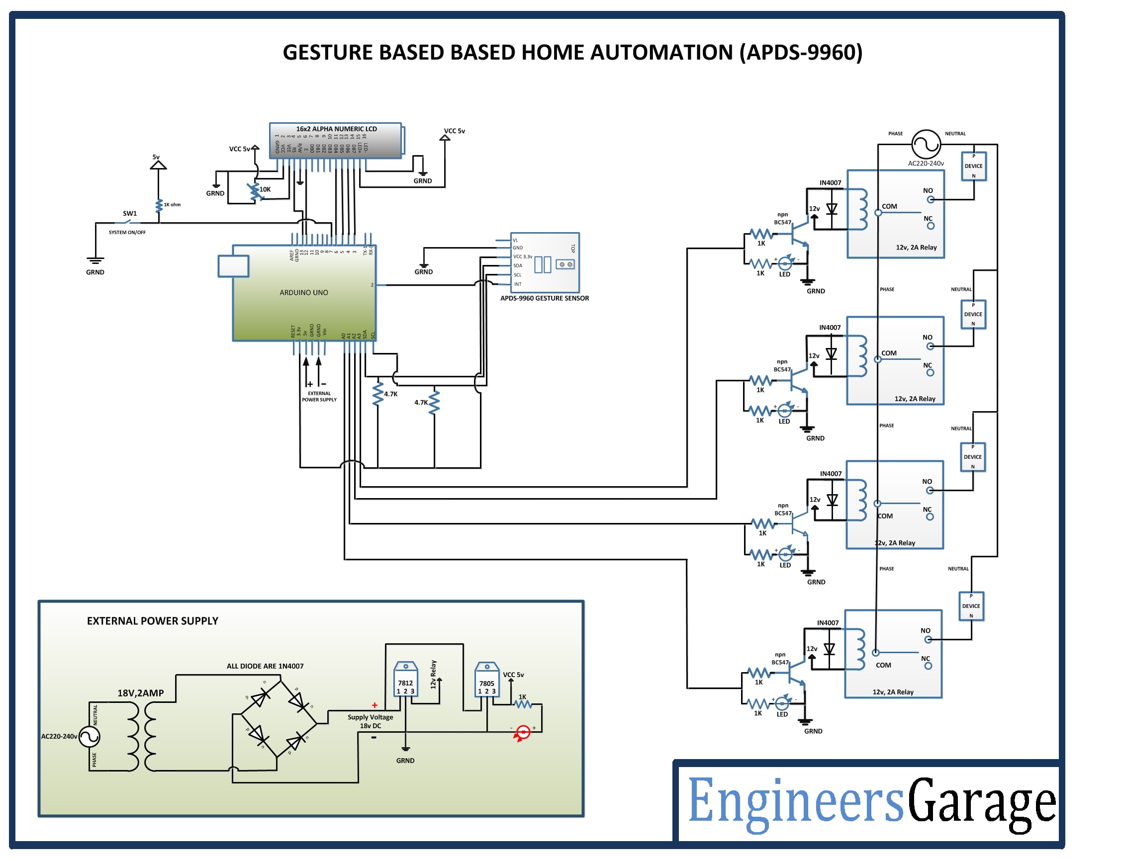
Circuit Diagrams
Project Video
Filed Under: Electronic Projects
Filed Under: Electronic Projects

Questions related to this article?
👉Ask and discuss on Electro-Tech-Online.com and EDAboard.com forums.
Tell Us What You Think!!
You must be logged in to post a comment.