Engineers Garage

  • Projects and Tutorials
    • Electronic Projects
      • 8051
      • Arduino
      • ARM
      • AVR
      • PIC
      • Raspberry pi
      • STM32
    • Tutorials
    • Circuit Design
    • Project Videos
    • Components
  • Articles
    • Tech Articles
    • Insight
    • Invention Stories
    • How to
    • What Is
  • News
    • Electronic Products News
    • DIY Reviews
    • Guest Post
  • Forums
    • EDABoard.com
    • Electro-Tech-Online
    • EG Forum Archive
  • Digi-Key Store
    • Cables, Wires
    • Connectors, Interconnect
    • Discrete
    • Electromechanical
    • Embedded Computers
    • Enclosures, Hardware, Office
    • Integrated Circuits (ICs)
    • Isolators
    • LED/Optoelectronics
    • Passive
    • Power, Circuit Protection
    • Programmers
    • RF, Wireless
    • Semiconductors
    • Sensors, Transducers
    • Test Products
    • Tools
  • EE Resources
    • DesignFast
    • LEAP Awards
    • Oscilloscope Product Finder
    • White Papers
    • Webinars
  • EE Learning Center
    • Design Guides
      • WiFi & the IOT Design Guide
      • Microcontrollers Design Guide
      • State of the Art Inductors Design Guide
  • Women in Engineering

GETTING STARTED WITH ESP8266 WIFI TRANSCEIVER

By Prabakaran P.M

ESP8266 is a UART to WiFi module which provides an easy way to connect any small Microcontroller platform like Arduino to Internet wirelessly. Since ESP8266 super cheap, and super easy to work with it become one of the leading platforms for the Internet of Things. You can use AT commands to connect to WiFi networks and open TCP connections without running TCP/IP stack. It also includes 32Bit Microcontroller which can be programmed to act as a standalone WiFi connected Embedded Platform.

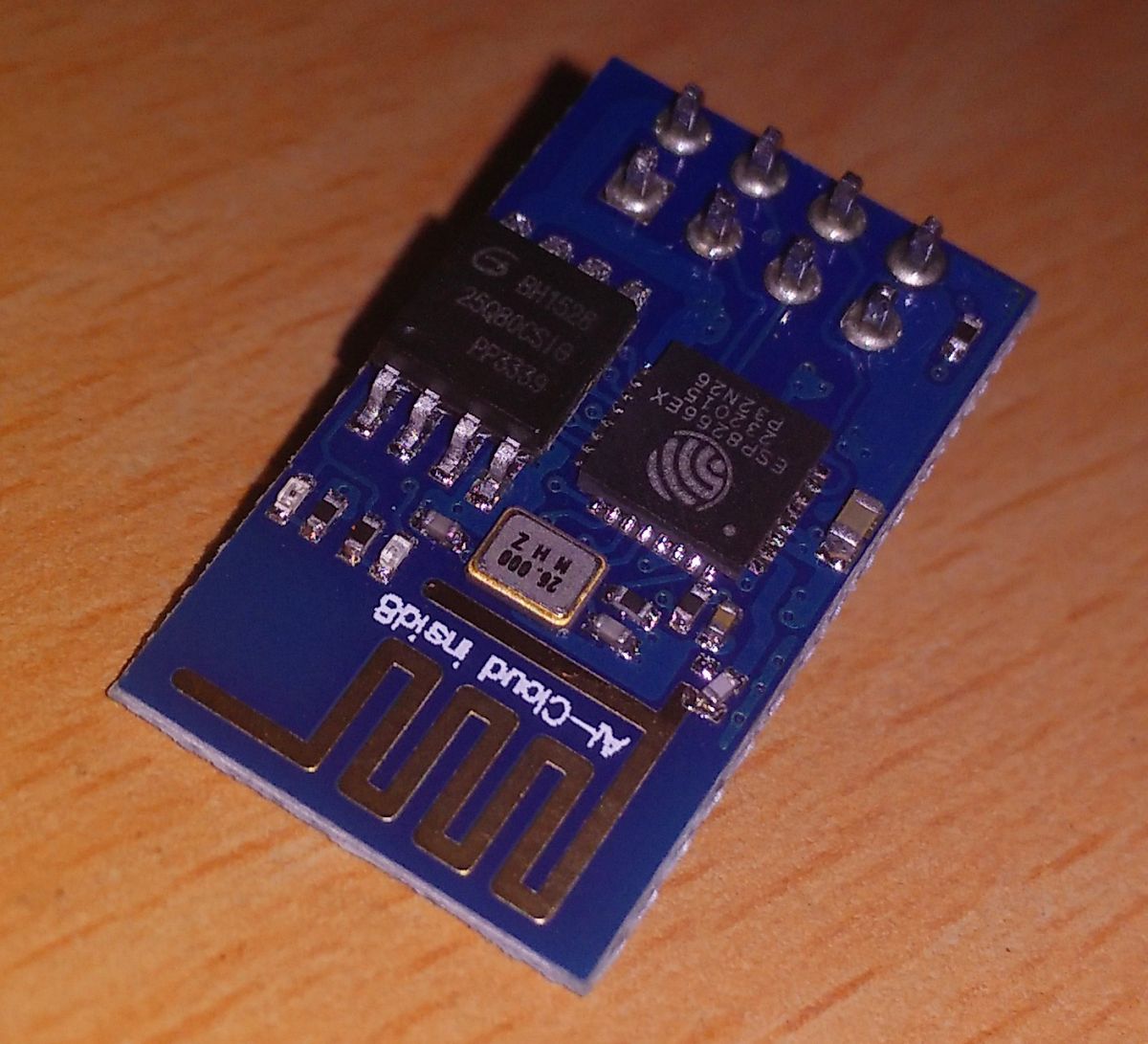
Fig. 1: Image of ESP8266 Wifi Tranceiver

So far there are different variants of ESP-x modules are available, Where x can be 1 to 12.

We are going to use the ESP-1 module with the new firmware which is set at 115200 baud.

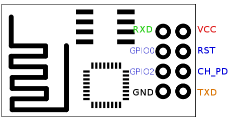
Fig. 2: Image showing PCB Layout of ESP-01 ESP8266 Module

ESP8266 requires 3.3v device, it can’t tolerate 5V so do not power it with 5Volts. We have to make sure that CH_PD pin is pulled up, the module will not give any response until you make this connection. This can be done either directly connecting CH_PD to VCC or you can also use the 3.3K resistance to pull up. The current rating of this Module is 80mA in idle and 300mA during operation.

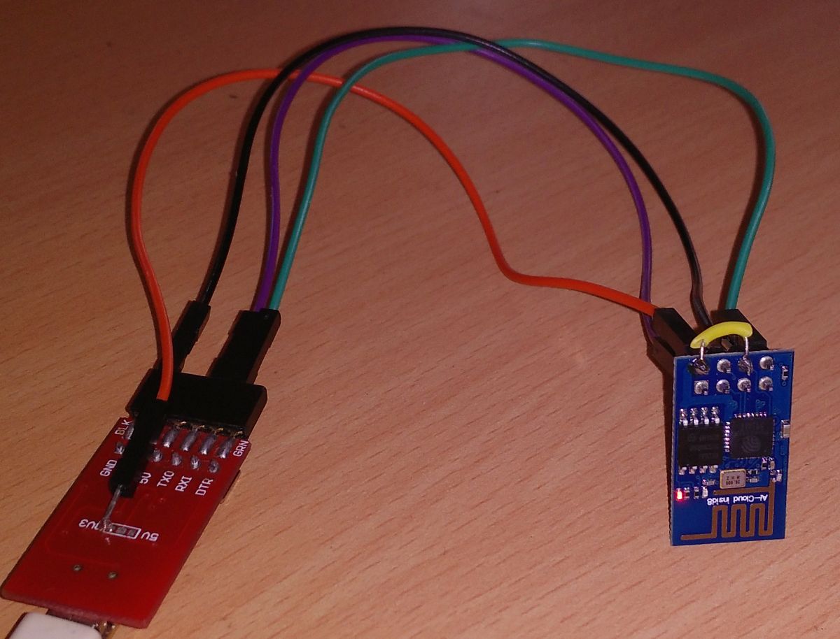
Fig. 3: Image showing Circuit Connections between ESP8266 Module and FTDI Converter


Here we are using USB to TTL converter for connecting the Module with the PC. The 3.3V output of the converter is used to power the module.

The connection details are as below:

WIFI Module

USB-TTL


Vcc

3.3v

Gnd

Gnd

TX

RX

RX

TX

CH_PD

Connected to 3.3v to enable chip firmware boot

Don’t forget to pull up CH_PD HIGH, you won’t get a response from the module if it is not done.

You can also use Arduino UNO by uploading empty setup() and loop() functions, if you don’t have a USB-TTL converter. 


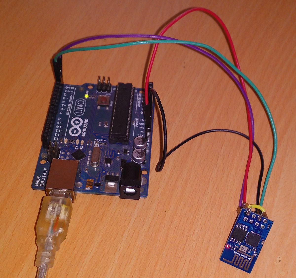
Fig. 4: Prototype of ESP8266 Wifi Tranceiver with Arduino Uno


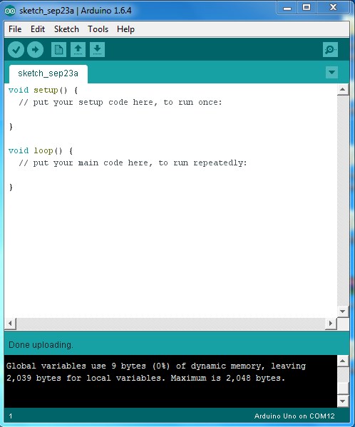
Fig. 5: Screenshot of Arduino IDE

The connection details are as below:

  WIFI Module

Arduino UNO


Vcc

3.3v

Gnd

Gnd

TX

TX

RX

RX

CH_PD

Connected to 3.3v to enable chip firmware boot


For viewing the data from the ESP8266 a serial terminal in Arduino IDE can be used.

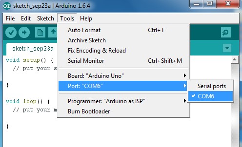
Fig. 6: Screenshot of Selecting a Port for Communication with ESP8266 on Arduino IDE


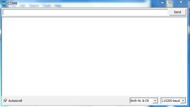
Fig. 7: Screenshot of Serial Terminal on Arduino IDE

Type in AT and press Enter. If you do not get any response, Reset the module by momentarily connecting the RST pin to GND and close the Serial window & again open it. Now type in AT and press Enter. The module will respond with OK. 

Fig. 8: Screenshot of AT Command passed from Arduino Serial Terminal

To know the current firmware version type AT+GMR and press Enter.

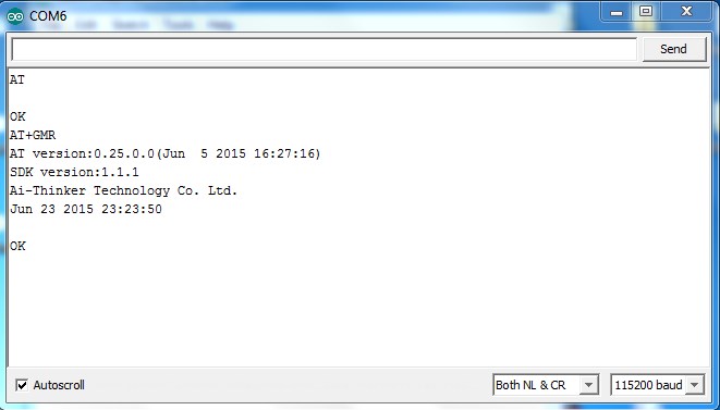
Fig. 9: Screenshot of AT+GMR Command passed from Arduino Serial Terminal

For inquiring the module about something you can use question mark “?” and you can use equal to “=” to assign a value after some AT commands.

For details related to AT commands visit :

 http://room-15.github.io/blog/2015/03/26/esp8266-at-command-reference/

To know the current mode of operation you can use AT+CWMODE?

CWMODE returns an integer which corresponds the mode of operation.

1 – Station mode (client)

2 – AP mode (host)

3 – AP + Station mode (Dual mode) 

Fig. 10: Screenshot of AT+GMR Command passed from Arduino Serial Terminal

To get the list of available WiFi access points you can use the command AT+CWLAP.

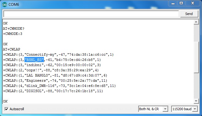
Fig. 11: Screenshot of AT+CWLAP Command passed from Arduino Serial Terminal

The Access Points are listed in the format which consists four parameters

+CWLAP: ecn, ssid, rssi, mac

The Parameter are

ecn: It is a number denoting the security of the Access point

0 – OPEN

1- WEP

2 – WPA_PSK

3 – WPA2_PSK

4 – WPA_WPA2_PSK

ssid: Denotes the SSID name of the Access point.

mac: It gives the MAC Address in a String value.

rssi: Gives the numerical value of the Signal Strength.

Use the command AT+CWMODE=1 to configure the module as STA or WiFi client that will connect to the router or Access Point. The module should be restarted to activate this selection.

AT+CWJAP=”yourSSID”,”yourWifiPassword”

This command is used to connect to your Access point, change your SSID and Password.

ESP module has the special property to remember the joined AP and it will reconnect to it after every successful Boot. AT+CWQAP command can be used to forget it.

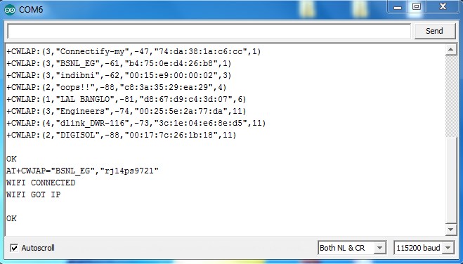
Fig. 12: Screenshot of AT+CWJAP Command passed from Arduino Serial Terminal

To know the IP address of the module after the successful connection, use the command AT+CIFSR it will give the IP address.

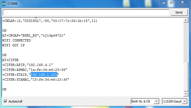
Fig. 13: Screenshot of AT+CIFSR Command passed from Arduino Serial Terminal

Open RUN in the windows system and type ping “your ip address” –t

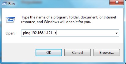
Fig. 14: Screenshot of Run Window with Command passed to ping IP Address

If all things went smooth new command window should open and start pinging with the ESP8266.

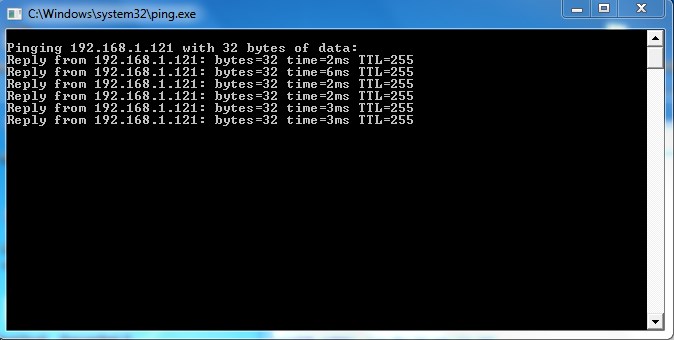
Fig. 15: Screenshot of Response from ESP8266 Module


Filed Under: Tutorials


Questions related to this article?
👉Ask and discuss on Electro-Tech-Online.com and EDAboard.com forums.


Tell Us What You Think!! Cancel reply

You must be logged in to post a comment.

HAVE A QUESTION?

Have a technical question about an article or other engineering questions? Check out our engineering forums EDABoard.com and Electro-Tech-Online.com where you can get those questions asked and answered by your peers!


Featured Tutorials

  • Introduction to Brain Waves & its Types (Part 1/13)
  • Understanding NeuroSky EEG Chip in Detail (Part 2/13)
  • Performing Experiments with Brainwaves (Part 3/13)
  • Amplification of EEG Signal and Interfacing with Arduino (Part 4/13)
  • Controlling Led brightness using Meditation and attention level (Part 5/13)
  • Control Motor’s Speed using Meditation and Attention Level of Brain (Part 6/13)

Stay Up To Date

Newsletter Signup

Sign up and receive our weekly newsletter for latest Tech articles, Electronics Projects, Tutorial series and other insightful tech content.

EE Training Center Classrooms

EE Classrooms

Recent Articles

  • What are the battery-selection criteria for low-power design?
  • Key factors to optimize power consumption in an embedded device
  • EdgeLock A5000 Secure Authenticator
  • How to interface a DS18B20 temperature sensor with MicroPython’s Onewire driver
  • Introduction to Brain Waves & its Types (Part 1/13)

Most Popular

5G 555 timer circuit 8051 ai Arduino atmega16 automotive avr bluetooth dc motor display Electronic Part Electronic Parts Fujitsu ic infineontechnologies integratedcircuit Intel IoT ir lcd led maximintegratedproducts microchip microchiptechnology Microchip Technology microcontroller microcontrollers mosfet motor powermanagement Raspberry Pi remote renesaselectronics renesaselectronicscorporation Research samsung semiconductor sensor software STMicroelectronics switch Technology vishayintertechnology wireless

RSS EDABOARD.com Discussions

  • 12V 5A needed
  • Vco cadencd
  • Slope compensation ramp calculation for UCC38084
  • Parts storage / inventory best practices and organization
  • Unusual gap shape of ETD59 ferrite core?

RSS Electro-Tech-Online.com Discussions

  • HV Diodes
  • intro to PI
  • surge arresters
  • NOR gate oscillator in LTspice not working
  • Very logical explanation on low calue C3
Engineers Garage
  • Analog IC TIps
  • Connector Tips
  • DesignFast
  • EDABoard Forums
  • EE World Online
  • Electro-Tech-Online Forums
  • Microcontroller Tips
  • Power Electronic Tips
  • Sensor Tips
  • Test and Measurement Tips
  • 5G Technology World
  • About Us
  • Contact Us
  • Advertise

Copyright © 2022 WTWH Media LLC. All Rights Reserved. The material on this site may not be reproduced, distributed, transmitted, cached or otherwise used, except with the prior written permission of WTWH Media
Privacy Policy | Advertising | About Us

Search Engineers Garage

  • Projects and Tutorials
    • Electronic Projects
      • 8051
      • Arduino
      • ARM
      • AVR
      • PIC
      • Raspberry pi
      • STM32
    • Tutorials
    • Circuit Design
    • Project Videos
    • Components
  • Articles
    • Tech Articles
    • Insight
    • Invention Stories
    • How to
    • What Is
  • News
    • Electronic Products News
    • DIY Reviews
    • Guest Post
  • Forums
    • EDABoard.com
    • Electro-Tech-Online
    • EG Forum Archive
  • Digi-Key Store
    • Cables, Wires
    • Connectors, Interconnect
    • Discrete
    • Electromechanical
    • Embedded Computers
    • Enclosures, Hardware, Office
    • Integrated Circuits (ICs)
    • Isolators
    • LED/Optoelectronics
    • Passive
    • Power, Circuit Protection
    • Programmers
    • RF, Wireless
    • Semiconductors
    • Sensors, Transducers
    • Test Products
    • Tools
  • EE Resources
    • DesignFast
    • LEAP Awards
    • Oscilloscope Product Finder
    • White Papers
    • Webinars
  • EE Learning Center
    • Design Guides
      • WiFi & the IOT Design Guide
      • Microcontrollers Design Guide
      • State of the Art Inductors Design Guide
  • Women in Engineering