This is the Article which will provide all the information about the ESPlorer IDE using NodeMCU. And basic things to get started with. The ESPlorer IDE was created by 4refr0nt.
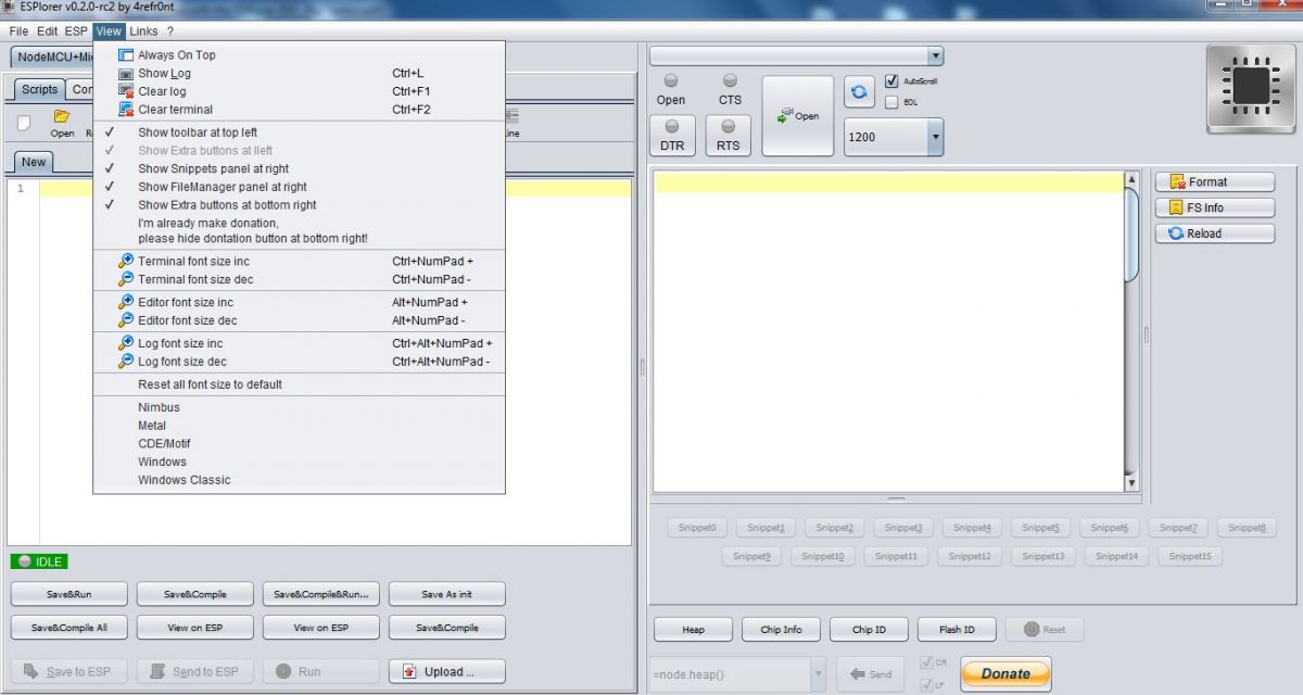
Fig. 1: Screenshot of ESPlorer IDE
Introduction:
The ESPlorer is an IDE for ESP development. It’s multiplatform, means that it runs on Windows, Mac OS X or Linux (it was created in JAVA).
Supported platforms:
-
Windows(x86, x86-64) s
-
Linux(x86, x86-64, ARM soft & hard float)
-
Solaris(x86, x86-64)
-
Mac OS X(x86, x86-64, PPC, PPC64)
This software allows you to establish a serial communication with your ESP8266, send commands, upload code and much more.
Requirements:
-
You need to have JAVA installed in your computer. If you are not having already, go to this website: http://java.com/download, download and install the latest version. It requires JAVA (SE version 7 and above) installed.
-
In order to complete the sample project presented in this Guide you need to flash your ESP8266 with NodeMCU firmware, here’s a blog post on how doing it: Flashing NodeMCU Firmware on the ESP8266.
Main Resources:
-
ESPlorer Homepage: http://esp8266.ru/esplorer/
-
GitHub Repository: https://github.com/4refr0nt/ESPlorer
Downloading ESPlorer :
Now let’s download the ESPlorer IDE, visit the following URL: http://esp8266.ru/esplorer/#download
Then click “Download ESPlorer” (as shown below).

Fig. 2: Screenshot of ESPlorer Download Page
Installing ESPlorer
Installing ESPlorer :
Grab the folder that you just downloaded. It should be named “ESPlorer.zip” and unzip it. Inside that folder you should see the following files:
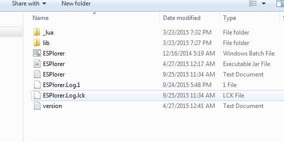
Fig. 3: Screenshot of ESPlorer.zip Files
Double click the “ESPlorer.jar” file and the ESPlorer IDE should open after a few seconds this is the file you need to open every time to work with the ESPlorer IDE.
Note: If you’re on Mac OS X or Linux you simply use this command to open the ESPlorer:
sudo java –jar ESPlorer.jar.
ESPlorer IDE :

Fig. 4: Screenshot of ESPlorer IDE
When the ESPlorer first opens, that’s what you should see:
Here’s a rundown of the features the ESPlorer IDE includes:
-
Syntax highlighting LUA and Python code
-
Code editor color themes: default, dark, Eclipse, IDEA, Visual Studio
-
Undo/Redo editors features
-
Code Autocomplete (Ctrl+Space)
-
Smart send data to ESP8266 (without dumb send with fixed line delay), check correct answer from ESP8266 after every lines.
-
Code snippets
-
Detailed logging
-
And a lot more
ESPlorer IDE Overview :
The ESPlorer IDE has a couple of main sections, let’s break it down each one.
In the top left corner you can see all the regular options that you find in any software. Create a New file, Open a new file, Save file, Save file as, Undo, Redo, etc.
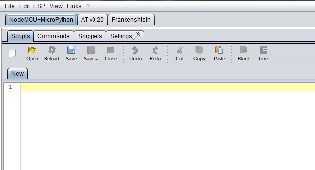
Fig. 5: Screenshot of Menus in ESPlorer IDE
In the top right corner you have all the options you need to establish a serial communication (you’re going to learn how to use them later in this Guide).

Fig. 6: Screenshot of Establishing a Serial Communication by ESPlorer
This next screenshot shows your Code Window, that’s where you write your scripts (your scripts are highlighted with your code sintax).
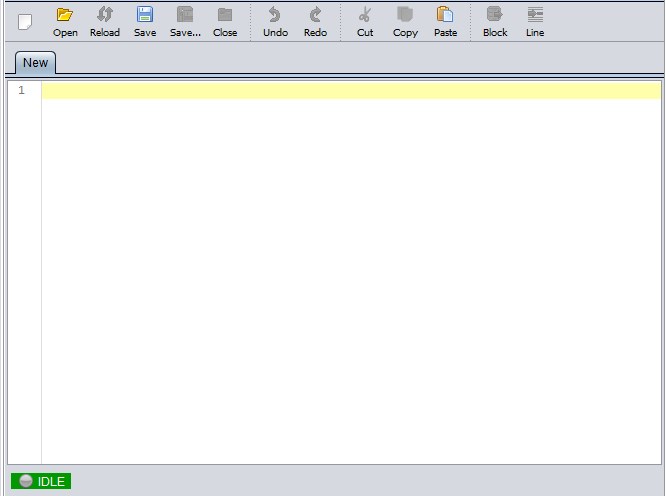
Fig. 7: Screenshot of Code Editor in ESPlorer
Below the Code Window, you have 12 buttons that offer you all the functions you could possibly need to interact with your ESP8266. Here’s the ones you’ll use most: “Save to ESP” and “Send to ESP”.
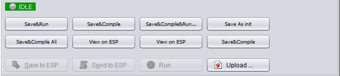
Fig. 8: Screenshot of GUI created from ESPlorer to Interact with ESP8266 Modem
This screenshot shows the Output Window which tells you exactly what’s going on in your ESP8266. You can see errors and use prints in your code to debug your projects.
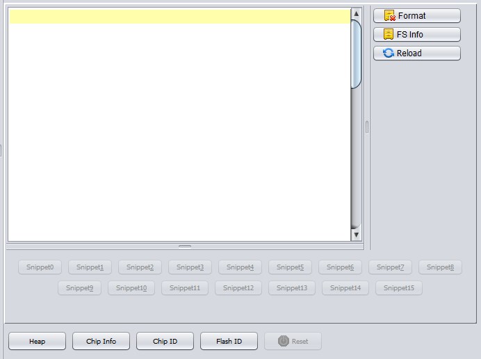
Fig. 9: Screenshot of Output Window in ESPlorer
To upload code to your ESP8266, you should connect your ESP8266 to your FTDI Programmer like the figure below:
Writing Your Lua Script:
Below is your script to blink an LED.
light=0
pin=4
gpio.mode(pin,gpio.OUTPUT)
tmr.alarm(1,1000,1,function()
if light==0 then
light=1
gpio.write(pin,gpio.HIGH)
else
light=0
gpio.write(pin,gpio.LOW)
end
end)
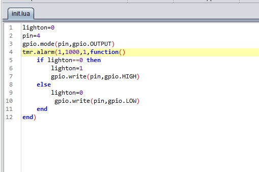
Fig. 10: Screenshot of C Code in ESPlorer
Uploading Code :
Having your ESP8266+FTDI Programmer connected to your computer, go to the ESPlorer IDE:
Connections for Normal mode:
The connection details are as below:
|
WIFI Module |
USB-TTL
|
|
Vcc |
3.3v |
|
Gnd |
Gnd |
|
TX |
RX |
|
RX |
TX |
|
CH_PD |
Connected to 3.3v to enable chip firmware boot |
Since two pins need to be connected to 3.3v it’s easiest to either use a breadboard with some connector cables. Connect LED to it, cathode (longer pin) to GPIO2 pin of the ESP8266 and anode (shorter pin) to the GND pin.
STEP 1: Look at the top right corner of your ESPlorer IDE and follow these instructions:
-
1. Press the Refresh button
-
2. Select the COM port for your FTDI programmer
-
3. Select your baudrate
-
4. Click Open
STEP 2: Then in the top left corner of your ESPlorer IDE, follow these instructions:
1. Select NodeMCU
2. Select Scripts
3. Create a new file called “init.lua”
STEP 3: Copy your Lua script (which you can find in the previous section) to the code window.
STEP 4: Saving your code to your ESP8266!
Click the button “Save to ESP” which is at the left bottom corner.
In your output window, it should start showing exactly which commands are being sent to your ESP8266 and it should look similar to the Figure below.
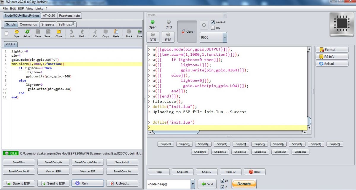
Fig. 11: Screenshot of Output Window in ESPlorer
Note: If you want to delete your “init.lua” file, you can do that easily. Simply type file.remove(“init.lua”) and press the button “Send” (see Figure above). Or you can type the command file.format() to remove all the files saved in your ESP8266. You can type any commands and send them to your ESP8266 through that window.
After uploading your code to your ESP8266, unplug your ESP8266 from your computer and Restart your ESP8266. Your LED should be blinking every 1 seconds!
Filed Under: Featured Contributions

Questions related to this article?
👉Ask and discuss on Electro-Tech-Online.com and EDAboard.com forums.
Tell Us What You Think!!
You must be logged in to post a comment.