In the previous tutorial, SIM800 module was configured as TCP-IP Client and a PC was configured as TCP-IP server. The two were setup to communicate over TCP-IP stack using an Arduino UNO as gateway. In this tutorial, the SIM800 will be configured as an MQTT Client and setup to communicate over MQTT protocol with a PC client. In the previous tutorial, the PC was configured as server to set SIM800 modem into working mode. In this project, the PC will serve as another client and communicate with the GSM GPRS modem via HiveMQ broker.
This project aims to build a communication network through which GPRS enabled IOT device could communicate with a remote PC. The IOT device is built using Arduino Mega and SIM800 GSM GPRS modem. The SIM800 chip does not have any controller inside, so it needs to be interfaced with a microcontroller to embed software intelligence for any application. On the other hand, Arduino Mega itself does not have capability to communicate with communication network (Internet). To connect the Arduino to the Internet, GPRS technology is used in this project which will provide internet connectivity to the Arduino client. Enabled with GPRS through SIM800 modem, the device does not need to connect with any Wi-Fi access point or LAN through Ethernet. Instead, it uses mobile network to access the internet. This greatly enhances the mobility and portability of the IOT device.
The Arduino and PC Clients communicate over MQTT protocol using HiveMQ broker. The implementation of MQTT protocol is only possible when the device has TCP/IP stack with itself. The GPRS has TCP/IP stack so the protocol can be easily implemented on it. The HiveMQ is a public MQTT broker and data can be communicated via this broker with unencrypted port 1883. The implementation of the protocol on Arduino client is performed from within the firmware code of the Arduino Mega. The Arduino sketch for this is written and compiled using Arduino IDE.
A remote PC acts as another IOT device in the project. The PC connects with the broker using a chrome add-on – MQTTLens. An LED is interfaced at the Arduino Client. The PC client controls this LED by passing messages to the Arduino Client over MQTT.
Components Required –

Fig. 1: List of components required for MQTT protocol based Mobile to PC IoT Communication
Software Required –
• Arduino IDE
• HiveMQ broker
Block Diagram –

Fig, 2: Block Diagram of SIM800 based GPRS Enabled Arduino LED Controller IOT Project
The PC connects with the broker using a chrome add-on. It does not need any external circuit for connecting with the MQTT broker. It connects with the internet using a Wi-Fi Access Point or Ethernet through a router.
Circuit Connections –
The Arduino based MQTT client is designed by interfacing an LED and SIM800 GSM GPRS Modem with the Arduino Mega.

Fig. 3: Prototype of SIM800 based GPRS Enabled Arduino LED Controller MQTT Client
The Arduino client has the following circuit connections –
SIM800 GSM GPRS Modem – SIM800 is the GSM GPRS modem used in this project. SIM800 is a complete Quad-band GSM/GPRS solution. It supports Quad-band 850/900/1800/1900 MHz and can transmit Voice, SMS and data information with low power consumption. The modem has the following pin configuration –

Fig. 4: Table listing pin configuration of SIM800 GSM GPRS Modem
Fig. 5: Table listing pin configuration of SIM800 GSM GPRS Modem
Fig. 6: Table listing pin configuration of SIM800 GSM GPRS Modem
Fig. 7: Table listing pin configuration of SIM800 GSM GPRS Modem
On a module, only some of the pins mentioned above may be available. Generally pins for audio interfacing, GPIO pins, power supply and serial communication are left available in the modules purchased from the market. The power supply (VCC and GND) and serial communication pins (TX and RX) are used to interface the modem in the circuit.
Fig. 8: Prototype of SIM800 based GPRS Enabled Arduino LED Controller MQTT Client
Power Supply – SIM800 modem needs 3.7 V and 2A to operate and connect with the Network properly. An external power supply is used to connect the modem to the network. The circuit connections of the GPRS module with the power source are summarized in the table below –

Fig. 9: Table listing circuit connections between SIM800 Modem and Power Supply
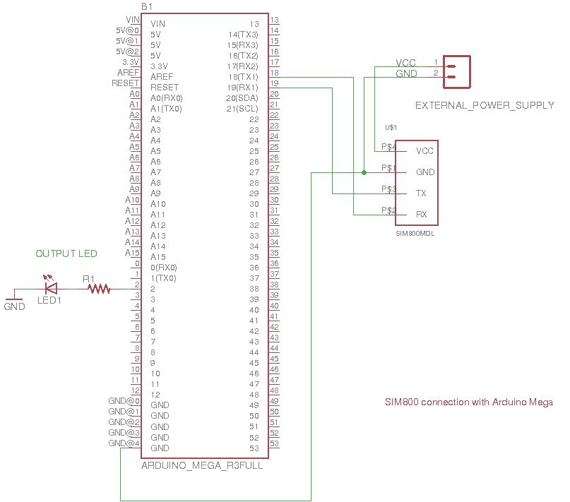
Arduino Mega – Arduino Mega is one of the microcontroller boards available on the Arduino platform. This controller board has Atmega 1280 as the sitting MCU and has 128 Kb flash memory, 4 Kb EEPROM, 8 Kb SRAM, onboard UART, SPI and I2C interfaces. The board has 56 GPIO pins of which 15 pins can be used for 8-bit PWM output. There are 16 analog input pins available on the board as well. The Arduino board controls the LED interfaced to it according to the data received by it over MQTT protocol. The SIM800 modem receives the data over internet using GPRS network which is passed through serial communication to the Arduino board. For serial communication, the TX1 (pin 18) and RX1 (pin 19) of the Arduino are connected with the RX and TX pins of the GSM GPRS module respectively. The circuit connections between the SIM800 module and Arduino board are summarized in the table below –
Fig. 10: Table listing circuit connections between SIM800 Modem and Arduino Mega
LED – An LED is interfaced at the pin 2 of the Arduino Mega. The anode of the LED is connected to the Arduino pin and cathode to the ground via a series resistor of 220 ohms.
On the PC side install the MQTTLens on the chrome browser. MQTTlens supports MQTT protocol and can be used for publishing and subscription of message. PC client should be assigned with unique client ID so that MQTT broker can easily identify which client is publishing and subscribing the topic and payload. Learn more about configuring PC as MQTT Client from the following tutorial –
Learn about creating and subscribing topics on HiveMQ broker and publishing messages on them from the following tutorial –
Communication between PC and Mobile using MQTT Protocol Via HiveMQ Broker
While making circuit connections, the following precautions must be taken care –
1) The SIM800 module needs 3.7 V voltage and 2A current. Please use external power supply to provide power to the modem. If the module is getting enough voltage but still not getting connected to the network, then there can be issue of current rating. The module is not getting enough current to operate in working condition. So, be specific while choosing the power source.
2) The modem has 5V tolerant input level but most of the modules work on CMOS logic. So, do not connect TX and RX of Arduino to the TX and RX of GSM modem because Arduino works on TTL logic for signal voltage. A bi-directional logic converter should be used in order to work with Arduino.
3) The SIM800 modem has a network indicator LED which tells about the modem connection to the network. If module is not connected to the network, the LED blinks every 1 second which means SIM is not connected to the network and is searching for the network. If the module is connected to the network, the LED blinks every 3 seconds. If the module is connected to the TCP/IP network, the LED blinks 3 times every second.
4) Check the network coordinates of the GSM modem through AT command AT+CREG? If the modem shows +creg: 0, 1 then the modem is connected to the network and no need to change in the library. But if the modem shows +creg: 1, 1, then the CREG condition need to be changed in the SIM800.cpp file in the SIM800 library. So, first check the network coordinates through AT commands.

Fig. 11: Screenshot of MQTTLens New Connection Window
How the circuit works –
The Arduino client is programmed to communicate with the PC client over MQTT protocol. For the implementation of MQTT protocol, an open source library (shown as PubSubClient in the Archive) is used. For the serial communication between the Arduino and SIM800, another open source library (shown as sim800 in the Archive) is imported in the IDE. There are additional libraries imported to provide time delay functions.
After loading the firmware and circuit connections, a SIM should be inserted in the GSM GPRS modem and the Arduino client should be powered on. Now the Arduino Client is ready to receive data over MQTT protocol from the GPRS network. The PC client is also ready to send control commands via MQTTLens add-on. The Arduino and PC clients communicate and send messages to each other via a MQTT broker called HiveMQ.
The Arduino client configures as publisher for the topic “GPRS_pub” and as subscriber for the topic “GPRS_sub/LED_control”. The PC client configures as subscriber for the topic “GPRS_pub” and as publisher for the topic “GPRS_sub/LED_control”. The Arduino Client initiates connection by publishing a message ‘ Welcome to GPRS NETWORK! ‘ to the MQTT broker.
When the PC client receives the message, it can publish messages ‘1’ and ‘0’ on the topic “GPRS_sub/LED_control”. If the message 1 is published by the PC client, it will be received by the Arduino client and its firmware code interprets the message to switch on the LED light. If the message 0 is published by the PC client, it will be received by the Arduino client and its firmware code interprets the message to switch off the LED light.
Programming Guide –
The Arduino client and PC client are connected to each other via HiveMQ broker and are communicating with each other. The PC client is controlling the LED of the Arduino client. The Arduino client is communicating with MQTT broker with the help of SIM800 modem. So, the modem needs to be connected to the GPRS network and then to the Internet. The APN, username and password for the SIM card must be initialized in the code. The following code is used to define the APN, username and password.
//Initialize the SIM to connect to the Network
#define SIM_APN “Airtelgprs.com” //APN Name, We are using Airtel network
#define SIM_USER “” //APN USER, We haven’t set any username so leave it blank
#define SIM_PASSWORD “” //APN PASSWORD, We haven’t set any password so leave it blank
The modem establishes TCP/IP connection to connect with Internet. The following function is called to initiate connection of the modem with the internet –
while (!s800.TCPstart(SIM_APN,SIM_USER,SIM_PASSWORD))
{
Serial.println(“TCPstart failed”);
s800.TCPstop();
delay(1000);
}
Serial.println(“TCPstart started”);
In this way the SIM800 modem connects to the Internet and provides connectivity to the Arduino client. Now, the modem initiates the connection with the MQTT broker so that Arduino client can communicate with PC client. The following code in the Arduino sketch is used to define the MQTT broker to which the Arduino has to communicate –
/*
MQTT broker on which our device is going to be connected!
We are using hiveMQ public broker with unencrypted channel
We can change the broker according to our requirement
*/
char server[] = “broker.mqttdashboard.com”;
The following function is called to handle the connection with the MQTT broker –
PubSubClient client(server, 1883, receive_message, s800);
Now the Arduino client is connected to the MQTT broker, the client registers the topic to the MQTT broker so that it can publish message on that particular topic. The PC client has subscribed to the same topic. So, this client receives the message from MQTT broker in a repetitive period of 5 seconds as the Arduino client is publishing the message in a duration of 5 sec. The following code is used to publish messages on the topic ‘ GPRS_pub’ –
/*@fn client.publish(Topic, message);
@Param: Topic, message
Topic- The topic on which our message is going to be published
Message- Any message on the respective topic
@brief: Call this function to publish the message on MQTT broker
*/
client.publish(“GPRS_pub”,”Welcome to GPRS NETWORK!”);
The PC client has subscribed to the same topic and is receiving messages on it after connecting with the MQTT broker.

Fig. 12: Screenshot of MQTT message received on PC Client from Arduino Client via HiveMQ Broker
The PC client is also publishing the message 0 or 1 on the topic “GPRS_sub/LED_control”. The Arduino client has subscribed to the same topic. Whenever the Arduino client receives any message on the subscribed topic, it calls receive_message() function. This is a callback function and it is called whenever an event occurs and the code written in this function is executed at that time. The Arduino client has subscribed to the topic using the following code –
client.subscribe(“GPRS_sub/LED_control”);
The following code is executed whenever the Arduino client receives the message –
void receive_message(char* topic, byte* payload, unsigned int length)
{
/*
When the client receives message 1, LED will be in ON state
When the client receives message 0, LED will be in OFF state
*/
if ((char)payload[0]== ‘1’)
digitalWrite(2, HIGH);
else if ((char)payload[0]== ‘0’)
digitalWrite(2, LOW);
}
When the PC client publishes the message “1”, the LED at the Arduino client starts glowing as the pin interfacing the LED is set to HIGH. When the PC client publishes the message “0”, the LED at the Arduino client stops glowing as the pin interfacing the LED is set to LOW.

Fig. 13: Screenshot of MQTT message sent from PC Client to Arduino Client via HiveMQ Broker
In this way, the Arduino Client and the PC Client communicate over MQTT protocol. The Arduino client is sharing its message to PC client and PC client is controlling the LED of the Arduino client. The Arduino Client access the internet through GPRS while the PC client access the internet via router either by using a Wi-Fi Access Point or Ethernet.
In the next tutorial, the basics of TCP protocol will be discussed.
You may also like:


Project Source Code
### //Program to /* @Project: SIM800_communication_over_MQTT_protocol @Hardware used: SIM800 Module Arduino Mega 2560 LED & 220E resistor External Power supply to provide 3.7V to SIM800 module @Connection: SIM800 VCC- External power supply 3.7V SIM800 GND- External power supply GND SIM800 TX- Arduino Serial1 RX SIM800 RX- Arduino Serial1 TX SIM800 GND- Arduino GND LED cathode- Arduino 2nd pin with 220E resistor in Series LED anode- Arduino GND External power supply GND- Arduino GND @Brief Introduction: In this application, We have used SIM800 as our first MQTT client and PC(MQTTlens) as our second MQTT client. We are using hiveMQ as our MQTT broker. We are using Arduino Mega to provide serial communication to SIM800 client. PC client is controlling the LED of SIM800 client & SIm800 client is publishing the message "Welcome to GPRS NETWORK!" on topic "GPRS_pub" */ //Initialize the SIM to connect to the Network #define SIM_APN "Airtelgprs.com" //APN Name, We are using Airtel network #define SIM_USER "" //APN USER, We haven't set any username so leave it blank #define SIM_PASSWORD "" //APN PASSWORD, We haven't set any password so leave it blank //Include Libraries #include#include //Include library to initialize SIM800 client #include //Include library to initlize MQTT protocol #include //Create the instance for SIM800 sim800Client s800; char imeicode[16]; //Array initialization for IMEI code so as to find out the device is valid or not. /* MQTT broker on which our device is going to be connected! We are using hiveMQ public broker with unencrypted channel We can change the broker according to our requirement */ char server[] = "broker.mqttdashboard.com"; /* @fn: void callback(char* topic, byte* payload, unsigned int length) @Param: topic, payload, payload length Topic: the subsription topic, SIM800 client has subscribed payload: the message we receive from MQTT broker on the subcribed topic length: the message length @return: None @brief: This callback function will be called whenever SIM800 client receives the message on topic GPRS_sub/LED_control */ void receive_message(char* topic, byte* payload, unsigned int length) { //handle message arrived char mypl[48]; Serial.println(length); memcpy(mypl,payload,length); mypl[length]=char(0); Serial.print("receive: "); Serial.print(topic); Serial.print("->"); Serial.println(mypl); /* When the client receives message 1, LED will be in ON state When the client receives message 0, LED will be in OFF state */ if ((char)payload[0]== '1') digitalWrite(2, HIGH); else if ((char)payload[0]== '0') digitalWrite(2, LOW); } /* @Create the instace for pubsub client @Param: server- MQTT server which we have initialized above 1883- The port on which MQTT broker is listening callback- The function for subscription which we have initialized above s800- SIM800 client which we have created above */ PubSubClient client(server, 1883, receive_message, s800); /* @fn void pub() @Param: None @Brief: Created a function through which S800 client will publish the message with topic to the MQTT broker Whenever we want to change the publish topic and message, we can change from here. @return: None */ void publish_message() { Serial.print("publish: "); Serial.print("message on topic GPRS_pub"); Serial.print("-> "); Serial.println("Welcome to GPRS NETWORK!"); /* @fn client.publish(Topic, message); @Param: Topic, message Topic- The topic on which our message is going to be published Message- Any message on the respective topic @brief: Call this function to publish the message on MQTT broker */ client.publish("GPRS_pub","Welcome to GPRS NETWORK!"); } void setup() { pinMode(2, OUTPUT); //Initialize LED as OUTPUT so that other client can control this LED Serial.begin(9600); //Start the serial communication to debug the communication Serial.println("SIM800 MQTT TESTING"); for (int i=0; i<10; i++) { delay(5000); Serial.println("Initialize SIM800!"); #ifdef HARDWARESERIAL if (s800.init( 7, 6)) break; #else if (s800.init(&Serial1 , 7, 6)) break; //Initialize the serial communication for SIM800 #endif } Serial.println("SETUP SIM800!"); s800.setup(); //Initialize setup for SIM800 client s800.stop(); //stop any previous network connection of the SIM800 client s800.TCPstop(); //Stop any previous TCP connection of SIM800 client s800.getIMEI(imeicode); //Get the IMEI code of he SIM800 client Serial.print("IMEI: "); Serial.println(imeicode); //From this loop, Start the continuous TCP connection with APN, USERNAME and PASSWORD while (!s800.TCPstart(SIM_APN,SIM_USER,SIM_PASSWORD)) { Serial.println("TCPstart failed"); s800.TCPstop(); delay(1000); } Serial.println("TCPstart started"); //From this loop,the client will be connected to the Network while (!client.connect(imeicode)) { Serial.println("connect failed"); delay(1000); } Serial.println("connected"); /* @fn client.subscribe(Topic); @Param: Topic Topic- The topic on which we receive the message @brief: Call this function to subsribe the topic from MQTT broker */ client.subscribe("GPRS_sub/LED_control"); //From this function, the message will be published in a repetitive period of 5 sec to the MQTT broker Alarm.timerRepeat(5, publish_message); } void loop() { client.loop(); Alarm.delay(100); } ###
Circuit Diagrams
Project Video
Filed Under: IoT, IoT tutorials, Tutorials
Filed Under: IoT, IoT tutorials, Tutorials

Questions related to this article?
👉Ask and discuss on EDAboard.com and Electro-Tech-Online.com forums.
Tell Us What You Think!!
You must be logged in to post a comment.