This tutorial is about interfacing GPS(global positioning system) with arduino. I am going to interface skylab SKM53 GPS module with arduino uno. I will acquire the current coordinates(longitude and latitude), date and time and then display them on arduino serial monitor. This is basic tutorial on interfacing gps module with arduino, after it i will make some cool applications like vehicle navigation system, objects tracking over web/google maps using gps coordinates, timing applications by acquiring current date and time using gps module.
About Skm53 GPS Module
Skm53 gps module works properly when it is fully exposed to sky. For indoor applications skm53 gps module is not suitable. The useful data skm53 gps module can output is latitude and longitude, current date and time, speed if the gps module carrying object is moving. Skm53 works on UART serial interface(TTL). It operates at +5v power supply.
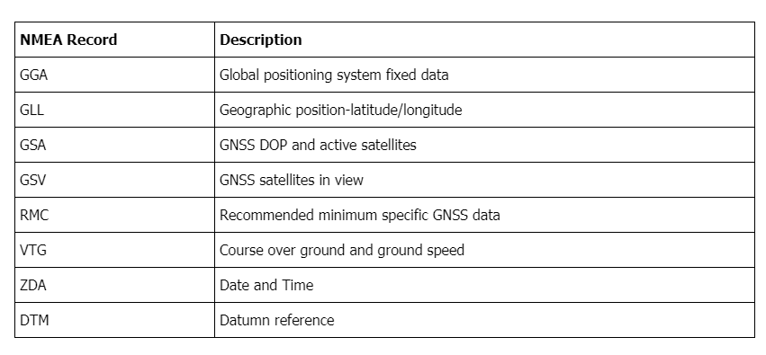
Skm53 outputs data as NMEA-0183 (National Marine Electronics Association) protocol. NMEA protocol outputs data against some commands such as GGA, GLL, GSA, GSV, RMC, VTG, ZDA and DTM. The module has its default NMEA-0183 factory output setting which is only GGA, GSA ,GSV, and RMC are operational and baud rate is set to 9600 bps.
NMEA commands and their functions
The output data by NMEA commands starts with $ sign and ends with carriage end line feed back. To learn about how to change the module baud rate, settings, commands their structure and how to enable and disable them? visit the link below.
Decoding NMEA commands OR getting data from commands output
To decode the output of NMEA statements a very complex program is required. Thanks to the unknown geeks which already developed a library(TinyGPS) compatible with arduino ide. The library TinyGPS can decode these NMEA statements and provide us with our desired information.
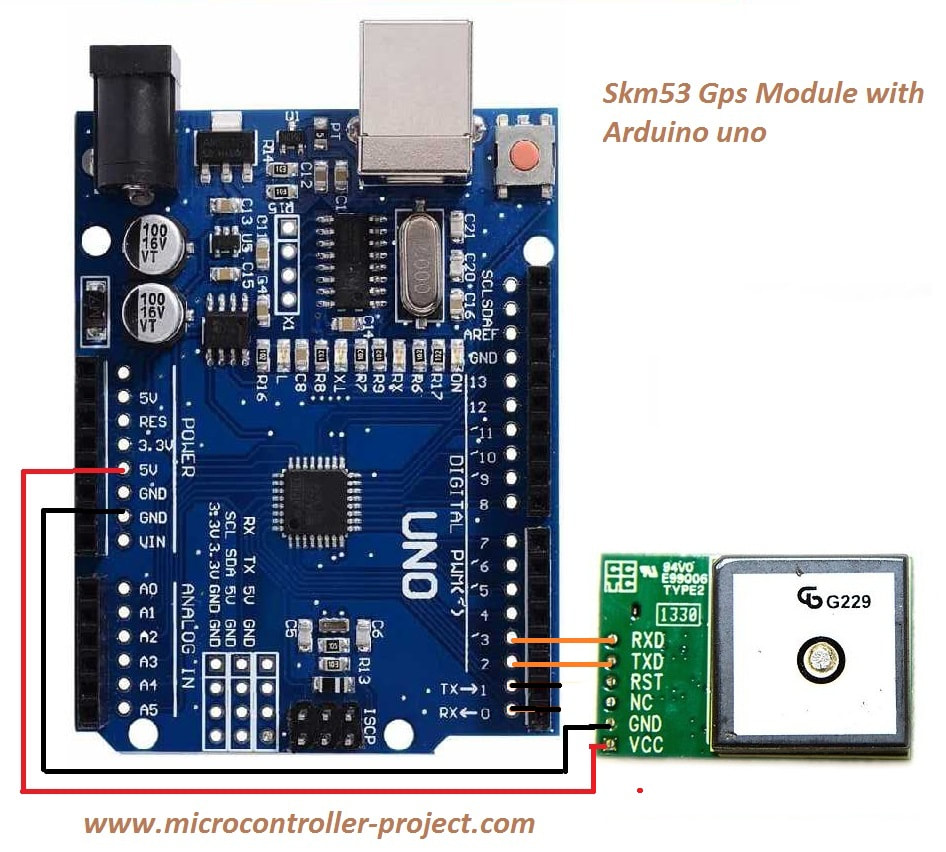
Arduino GPS module interface circuit diagram
Project circuit diagram is given below. Please note that arduino pin#2 and 3 are used for serial communication/interfacing with the skm53 gps module. This is because the pins 0 and 1 which are default arduino uart port is shared with the pc/laptop. So the default port is used to send data to pc/laptop for displaying on arduino serial monitor and pins 2 and 3 are used to communicate with gps module. I used softserial library to make arduino pins 2 and 3 as virtual uart port.
I powered the skm53 gps module with arduino +5v output. Some people said that this configuration doesn’t worked fro them. So i recommend to power the skm53 module with an external +5 volt power supply and connect arduino and external supply ground with each other for successful uart serial communication.
Download the project code.Folder contains project.ino file. Please provide us your feed back on the project. If you have any questions or queries please write them below in the comments section.
Watch the project video here
Filed Under: Arduino, Microcontroller Projects


Great tutorial! I used the 5V from my Uno to power the SKM53 but couldn’t get serial communication to work. I then put a 100uF filter cap on the 5v power supplied from the UNO and presto-magic, communication was established. I suspect that dirty power from my cheap Chinese Uno was the cause of this problem and perhaps those who also had issues with using power from the Uno can solve this with a filter cap.
Nice project !! I have ordered this Skylab module.
I have read the issue with the 5 volts to the module.
I will try to make a simple low-pass filter with a coil and a cap of 100uF.
Maybe the switching-frequency isn’t filtered enough on some boards.