Engineers Garage

  • Projects and Tutorials
    • Electronic Projects
      • 8051
      • Arduino
      • ARM
      • AVR
      • PIC
      • Raspberry pi
      • STM32
    • Tutorials
    • Circuit Design
    • Project Videos
    • Components
  • Articles
    • Tech Articles
    • Insight
    • Invention Stories
    • How to
    • What Is
  • News
    • Electronic Products News
    • DIY Reviews
    • Guest Post
  • Forums
    • EDABoard.com
    • Electro-Tech-Online
    • EG Forum Archive
  • Digi-Key Store
    • Cables, Wires
    • Connectors, Interconnect
    • Discrete
    • Electromechanical
    • Embedded Computers
    • Enclosures, Hardware, Office
    • Integrated Circuits (ICs)
    • Isolators
    • LED/Optoelectronics
    • Passive
    • Power, Circuit Protection
    • Programmers
    • RF, Wireless
    • Semiconductors
    • Sensors, Transducers
    • Test Products
    • Tools
  • EE Resources
    • DesignFast
    • LEAP Awards
    • Oscilloscope Product Finder
    • White Papers
    • Webinars
  • EE Learning Center
  • Women in Engineering

Interfacing Graphical LCD(GLCD-JHD12864E) with Microchip PIC16f877 Microcontroller

By EG Projects

In this post/tutorial i am going to teach you how to interface graphical lcd jhd12864E with microchip pic16f877 microcontroller. I am going to display my website name “www.microcontroller-project.com” and a special pattern that displays thick lines on dotted graphical lcd display. In graphical lcd name “jhd12864” the number 128×64 means lcd has 128 coulombs and 64 rows. On graphical lcd’s data(character, numbers) is displayed on dots. A joint between coulomb and row is termed as dot. Total dots present in jhd12864 lcd are 128 x 64 = 8192 dots. When dots are combined they make a dot cluster. This cluster of dots in square form is know as matrix. On these 8192 dots we can display/make our data(character, number, image). In graphical lcd’s we are free to make character’s of our desired size unless the size is in the matrix of graphical lcd. 

Before proceeding i would recommend you to please go through a small tutorial. This tutorial will helps you to understand how text is displayed on graphical lcd, how graphical lcd dots are arranged in pages, how graphical lcd is initialized(Graphical Lcd initializing commands), each and every pin of graphical lcd is deeply explained in the tutorial. You can easily understand the code below if you go through the tutorial. 

  • Graphical Lcd Pin Out and Working​​
Graphical LCD JHD12864

Graphical LCD JHD12864

Graphical Lcd with Pic Microcontroller – Project requirements

  • Microcontroller(Microchip Pic16f877)
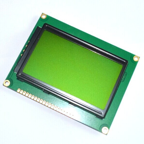
  • Graphical Lcd(JHD12864E)
  • Crystal (20MHZ)
  • Capacitors (30pf)
  • Potentiometer-Variable resistor(0-100k)
  • Connecting Wires
  • Power Source (Battery, Adapter etc)

Graphical Lcd which i am using is JHD12864E. It comes in 20 Pin Package. Pin out of JHD12864E is given below. Its an 8-bit lcd. It comes with two built in controllers. Each controller is selected with chip select pins (cs1 and cs2). ​Visit the tutorial link given above to properly understand the pin functions and how to use them properly.

JHD12864E(GLCD-Graphical Lcd) Lcd pinout

JHD12864E(GLCD-Graphical Lcd) Lcd pinout

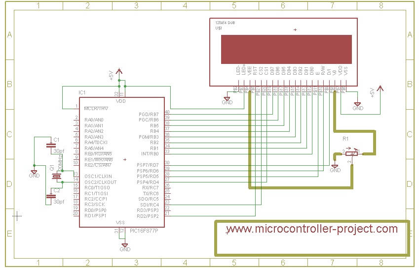
Graphical lcd with pic microcontroller – Project Circuit Diagram

Lcd data pins are connected to Port-B of pic16f877 microcontroller. Lcd is interfaced in 8-bit mode with microcontroller. RS(register select) Pin of Lcd is connected to Port-D pin#7. RW(Read/Write) Pin of Lcd is connected to Port-D Pin#6. EN(Enable) Pin of Lcd is Connected to Port-D pin#5. CS1(Chip select) Pin of Lcd is connected to Port-D pin#4. CS2(Chip select) of lcd is connected to Port-C pin#4. RST(Reset) pin of Lcd is Connected to Port-D pin#2. A variable resistor is used between pins VEE and V0. This variable resistor is very important, it sets the Lcd contrast. Just connect the resistor, vary the resistance by rotating the knob, Adjust the best quality of lcd display that suites you. You can view highly black colour dots by increasing the resistance. If you want to see fant text reduce the resistance. LED+ and LED- are back light pins. I usually switch on the back light same i did for this project.

All other connections are necessary connections to make controller work. Attach crystal(20Mhz) to controller in parallel to two 30pf capacitors. Supply +5v to vcc and vdd. Make GND ground. Circuit diagram of the project is give below.

JHD12864E  Graphical lcd interfacing with Pic16f877 Microcontroller

JHD12864E Graphical lcd interfacing with Pic16f877 Microcontroller

Coming to code portion. I write code in c++ language and used MPLAB-IDE with High Tech C compiler to compile code and generate Hex code.

  • Clearlcd() function is half-filling each page with dots. Both halfs pages are filled in up and down position. If 2nd page of 1rst half is filled from down then 2nd page of 2nd half is filled from up.
  • #define statements are defining pins as rs,rw,en etc. Now these pins can be accessed in code as rs,rw,en etc.
  • delay() function is used to generate some delay where required.
  • lcdcmd() is sending commands to lcd. It also manipulates lcd pins to successfully execute the command.
  • lcddata() is sending data to lcd. It also manipulates lcd pins to successfully display data on lcd.

Main() function contains the code that displays all stuff on lcd. First it jumps to clearLcd() function fills pages with dots. Then it displays my web site name on lcd. Pattern of each character of my site is commented in the code.

Visit next tutorial on how to display Images on GLCD Graphical Lcd with Pic Microcontroller.

Display Image on GLCD using Pic Microcontroller

Display Images on GLCD using 89c51 Microcontroller

Download the project files, folder contains the c code and hex file of the project. Simulation of the project is also included in the folder. Simulation is made in proteaus 8.0. Please give us your feed back on the post. If you have any queries please write them below.
Grahical Lcd with Pic Microcontroller files/code


Filed Under: Microcontroller Projects, PIC Microcontroller


Questions related to this article?
👉Ask and discuss on EDAboard.com and Electro-Tech-Online.com forums.


Tell Us What You Think!! Cancel reply

You must be logged in to post a comment.

HAVE A QUESTION?

Have a technical question about an article or other engineering questions? Check out our engineering forums EDABoard.com and Electro-Tech-Online.com where you can get those questions asked and answered by your peers!


Featured Tutorials

  • Adjustable 0 to 30V 2A DC Power Supply Circuit (Part 1/13)
  • Adjustable +/- 1.25V to +/-22V 1A Power Supply Circuit (Part 2/13)
  • Adjustable 0 to 15V 1A Mini Power Supply (Part 3/13)
  • Constant 12V Power Supply for LED Circuits (Part 4/13)
  • Constant +/-9V DC Symmetrical Power Supply Circuit (Part 5/13)
  • Making a Circuit Breaker (Part 6/13)

Stay Up To Date

Newsletter Signup

Sign up and receive our weekly newsletter for latest Tech articles, Electronics Projects, Tutorial series and other insightful tech content.

EE Training Center Classrooms

“ee

“ee

“ee

“ee

“ee

“ee

Recent Articles

  • STMicroelectronics and MACOM announce successful RF GaN-on-Si prototypes
  • Infineon expands its CoolSiC portfolio
  • STMicroelectronics and AWS collaborate for secure IoT connections
  • Pet feeding system using WhatsApp (protocol bridging with MQTT)
  • STMicroelectronics launches new MDmesh MOSFETs

Most Popular

5G 555 timer circuit 8051 ai Arduino atmega16 automotive avr dc motor display Electronic Part Electronic Parts Fujitsu ic infineontechnologies integratedcircuit Intel IoT ir lcd ldr led maximintegratedproducts microchip microchiptechnology Microchip Technology microcontroller microcontrollers mosfet motor powermanagement Raspberry Pi remote renesaselectronics Research robot samsung semiconductor sensor software STMicroelectronics switch Technology vishayintertechnology wireless

RSS EDABOARD.com Discussions

  • P-Channel MOSFET always on
  • Space Vector PWM Help Needed
  • Power Supply Design ideas Please for Mains LED Strip
  • Unable to launch virtuoso: libvisadev.so error
  • Help with Verilog replicate operator

RSS Electro-Tech-Online.com Discussions

  • XOR Gate Circuit From Diodes
  • 3.3V microcontroller vs 5V relay
  • How to get lots of PCBs made cheap?
  • What is this part on my solar controller
  • High component count for long delay circuit (inrush resistor switch out)
Engineers Garage
  • Analog IC TIps
  • Connector Tips
  • DesignFast
  • EDABoard Forums
  • EE World Online
  • Electro-Tech-Online Forums
  • Microcontroller Tips
  • Power Electronic Tips
  • Sensor Tips
  • Test and Measurement Tips
  • 5G Technology World
  • About Us
  • Contact Us
  • Advertise

Copyright © 2022 WTWH Media LLC. All Rights Reserved. The material on this site may not be reproduced, distributed, transmitted, cached or otherwise used, except with the prior written permission of WTWH Media
Privacy Policy | Advertising | About Us

Search Engineers Garage

  • Projects and Tutorials
    • Electronic Projects
      • 8051
      • Arduino
      • ARM
      • AVR
      • PIC
      • Raspberry pi
      • STM32
    • Tutorials
    • Circuit Design
    • Project Videos
    • Components
  • Articles
    • Tech Articles
    • Insight
    • Invention Stories
    • How to
    • What Is
  • News
    • Electronic Products News
    • DIY Reviews
    • Guest Post
  • Forums
    • EDABoard.com
    • Electro-Tech-Online
    • EG Forum Archive
  • Digi-Key Store
    • Cables, Wires
    • Connectors, Interconnect
    • Discrete
    • Electromechanical
    • Embedded Computers
    • Enclosures, Hardware, Office
    • Integrated Circuits (ICs)
    • Isolators
    • LED/Optoelectronics
    • Passive
    • Power, Circuit Protection
    • Programmers
    • RF, Wireless
    • Semiconductors
    • Sensors, Transducers
    • Test Products
    • Tools
  • EE Resources
    • DesignFast
    • LEAP Awards
    • Oscilloscope Product Finder
    • White Papers
    • Webinars
  • EE Learning Center
  • Women in Engineering