In present time there are many types of Home Automation Systems available in our market. Most of these are simple home appliances controlling systems like DTMF controlled home Appliances, IR Remote based home appliances controlling, RF based home appliances controlling. And here, we are going to discuss about GSM based Home/Office Appliances Control (Home Automation System).
This is a very common system, in which users can also use this system at farm house and house, offices for filling the water tanks. This system can also be used for start motor or Stop motor at defined time when water supply available.

Fig. 1: Image showing message sent to Arduino based Home Automation System

Fig. 2: Prototype of Arduino and GSM GPRS Module based Mobile Operated Home Automation System

Fig. 3: Image of Display panel on Arduino based Home Automation System
In this system Arduino is the heart of this system which takes control over whole the system process. So it is assumed that reader have knowledge about how to start with arduino. Here a GSM module is used for sending and receiving the message. A 16×2 liquid crystal LCD used with arduino for displaying the appliances status and process like SYSTEM READY, TV ON, light 1 ON, light 1 OFF, light 2 ON, light 2 OFF etc. Here AC load is used for demonstration. Three home/office appliances are used for demonstration. In which one zero watt bulb indicated by light 1 and second is 100 watt bulb indicated by light 2 and third and last is TV/LCD indicated by TV. In system has an additional function in which you will get the notification or status message on message sending number. Means if you sends message for ON OFF any electrical appliance by any mobile number then you will get status or notification message on the same mobile number.
Block Diagram

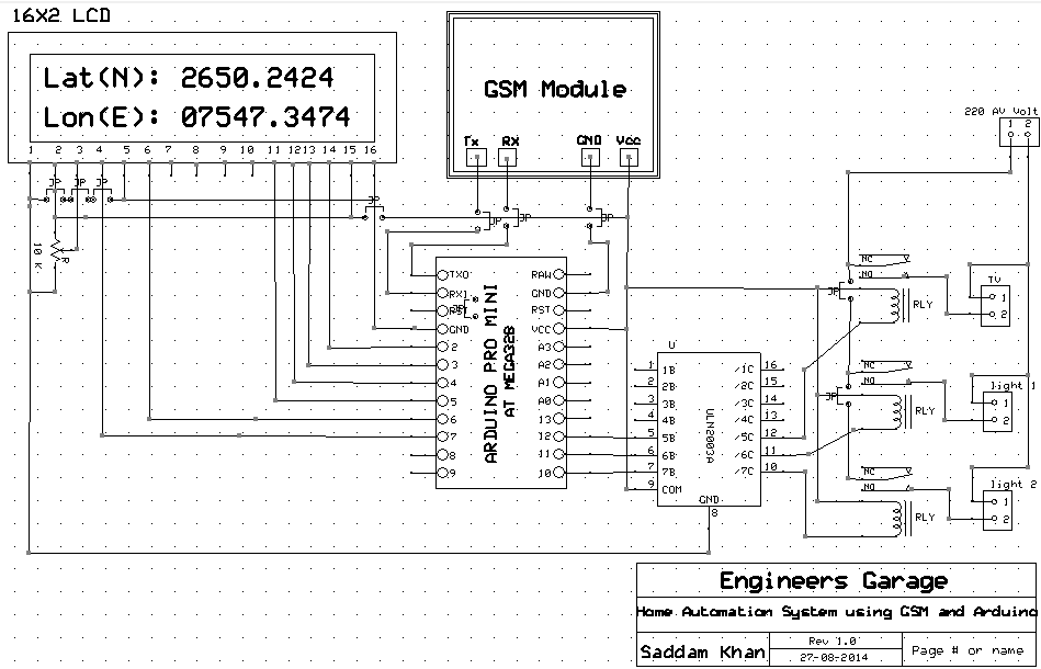
Fig. 4: Block Diagram of Arduino and GSM GPRS Module based Mobile Operated Home Automation System
If sender’s mobile number is 96101xxxxx, then sender will get notification on same means on 96101xxxxx.
And if sender’s mobile number is 82871xxxxx, then sender will get notification on same means on 82871xxxxx.
Circuit & Program Description
Circuit Description
GSM module’s pin Tx and Rx is directly connected with Rx and Tx pins of Arduino. And power supply adaptor is also connected with GSM module. The ground of both GSM and Arduino should be connected with each other otherwise system will not work properly. And relays are connected to digital pin 10, 11, 12 of Arduino for controlling light 1, light 2, TV respectively using ULN 2003 IC. ULN2003 is a high-voltage high-current Darlington transistor arrays. Each consists of seven NPN Darlington pairs that feature high-voltage outputs with common-cathode clamp diodes for switching inductive loads. And 5 volt relays are used here, which are best suitable for these types of Projects.
Light 1 is connected with relay 1, light 2 is connected with relay 2 and TV is connected with relay 3.

Fig. 5: Circuit Diagram of Relay Driver used in Home Automation System
Relay Connection Circuit for DC supply (connect AC supply in place of battery and electrical appliances in place of LED polarity does not affects in AC.)
You can add more home/office appliances with this system and by adding some functions in program you can control more. 16×2 LCD’s commands pins RS and EN is directly connected with pin 7 and 6 respectively and Data pins d4, d5, d6, d7 are connected with 5, 4, 3, 2 pins of Arduino.
Program Description
In programming some string are defined for comparing.
Ex:
String TV_ON=”TV ON”;
String TV_OFF=”TV OFF”;
String LIGHT1_ON=”light 1 ON”;
String LIGHT1_OFF=”light 1 OFF”;
String LIGHT2_ON=”light 2 ON”;
String LIGHT2_OFF=”light 2 OFF”;
Working & Components Used
Working
Working of this project is very simple. when we sends any message to system’s GSM module, this message is store in an array namely STR and then program extracts the mobile number and main message from it by using some programming methods. Mobile number is store in a string namely string number and main message which is kept in * and # is store in a string namely string name. After this process by using string matching function we match name string with defined strings and if match occurs, related function is performed and GSM sends back a related notification message to sender’s number, besides this LCD also displays the notification message.
Ex:
If in number string stored value after extracting is “82871xxxxx”
And in TV ON string is match with name string then TV will turn ON and GSM sends back a notification message like TV ON.
And likewise for another appliances
Extracting Mobile Number

Fig. 6: Screenshot of Arduino Code used to display numbers on display panel of Home Automation System
Extracting Main Message

Fig. 7: Screenshot of Arduino Code used to display messages on display panel of Home Automation System
Comparing of Two String and Sending Notification Message

Fig. 8: Screenshot of Arduino Code used to display status of home appliances
Components Used
2. GSM Module
3. Connecting Wires
4. Power Supply
5. AC Appliances
6. Relays
7. ULN2003
Project Source Code
###


#include<LiquidCrystal.h>

#define light1 10
#define light2 11
#define TV 12

int temp4=0;

LiquidCrystal lcd(7,6,5,4,3,2);
int lenth,lenth1,i=0,temp=0;

String str="";
String name="";
String number="";

String TV_ON="TV ON";
String TV_OFF="TV OFF";
String LIGHT1_ON="light 1 ON";
String LIGHT1_OFF="light 1 OFF";
String LIGHT2_ON="light 2 ON";
String LIGHT2_OFF="light 2 OFF";


void setup()
{
  lcd.begin(16,2);
  Serial.begin(9600);
  pinMode(13, OUTPUT);
   pinMode(light1, OUTPUT);
    pinMode(light2, OUTPUT);
     pinMode(TV, OUTPUT);

  lcd.setCursor(0,0);
  lcd.print("GSM Based Home/ ");
  lcd.setCursor(0,1);
  lcd.print("Office Aplliance");
  delay(2000);
  lcd.clear();
  lcd.setCursor(0,0);
  lcd.print("    Control     ");
  delay(2000);
  lcd.setCursor(0,0);
  lcd.print("By Saddam Khan  ");
  lcd.setCursor(0,1);
  lcd.print("Engineers Garage");
  delay(1000);
  Serial.println("AT+CNMI=2,2,0,0,0");
  Serial.println("AT+CMGF=1");
  delay(1000);
  lcd.clear();
}

void loop()
{

   while(temp!=0)
   {
    i=0;
    while(i<lenth)
    {
     if(str[i]=='"')
     {
       temp4++;
     }


     if(temp4==1)
     {
       for(int j=0;j<15;j++)

       {
         number+=str[i];
         i++;
       }
       temp4=2;
     }
     if(str[i]=='*')
     {
      i++;
      while(str[i]!='#')
      {
       name+=str[i];
       i++;
      }
     }
     i++;
    }


    chack();
   // lcd.setCursor(13,0);
   // lcd.print(name);
   // lcd.setCursor(0,1);
   // Serial.println(name);
   // Serial.println(number);
    //Serial.print("AT+CMGS=");
  //  Serial.println(number);
    delay(2000);

    temp=0;
    temp4=0;
    name="";
    lenth=0;
    str="";
    number="";
    delay(1000);
   }
    lcd.setCursor(0,1);
     lcd.print("System Ready");

    delay(400);
}

 void serialEvent()
{
  while (Serial.available())
  {
    char inChar = (char)Serial.read();
    str+=inChar;
     lenth++;
    if (inChar == 'n')
    {      temp=1;
      inChar=0;
}
}
}
void chack()
{
   if(name == TV_ON)
    {
      digitalWrite(TV, HIGH);
      Serial.println("AT+CMGF=1");
      delay(1);
      Serial.print("AT+CMGS=");
      Serial.println(number);
      delay(1);
      Serial.print("TV ON");
      Serial.write(26);
     lcd.clear();
      lcd.setCursor(0,0);
      lcd.print("TV ON");
      delay(2000);
    }

    if (name == TV_OFF)
    {
      digitalWrite(TV,LOW);
      Serial.println("AT+CMGF=1");
      delay(1);
      Serial.print("AT+CMGS=");
      Serial.println(number);
      delay(1);
      Serial.print("TV OFF");
      Serial.write(26);
    lcd.clear();
      lcd.setCursor(0,0);
      lcd.print("TV OFF");
      delay(2000);

    }

      if (name == LIGHT1_ON)
    {
      digitalWrite(light1,HIGH);
      Serial.println("AT+CMGF=1");
      delay(1);
     Serial.print("AT+CMGS=");
      Serial.println(number);
      delay(1);
      Serial.print("LIGHT 1 ON");
      Serial.write(26);
      lcd.clear();
      lcd.setCursor(0,0);
      lcd.print("LIGHT  1 ON");
      delay(2000);

    }

      if (name == LIGHT1_OFF)
    {
      digitalWrite(light1,LOW);
      Serial.println("AT+CMGF=1");
      delay(1);
      Serial.print("AT+CMGS=");
      Serial.println(number);
      delay(1);
      Serial.print("LIGHT 1 OFF");
      Serial.write(26);

      lcd.clear();
      lcd.setCursor(0,0);
      lcd.print("LIGHT 1 OFF");
      delay(2000);
    }
      if (name == LIGHT2_ON)
    {
      digitalWrite(light2,HIGH);
      Serial.println("AT+CMGF=1");
      delay(1);
     Serial.print("AT+CMGS=");
      Serial.println(number);
      delay(1);
      Serial.print("LIGHT 2 ON");

      Serial.write(26);
      lcd.clear();
      lcd.setCursor(0,0);
      lcd.print("LIGHT 2 ON");
      delay(2000);
    }


      if (name == LIGHT2_OFF)
    {
      digitalWrite(light2,LOW);
      Serial.println("AT+CMGF=1");
      delay(1);
      Serial.print("AT+CMGS=");
      Serial.println(number);
      delay(1);
      Serial.print("LIGHT 2 OFF");
      Serial.write(26);
      lcd.clear();
      lcd.setCursor(0,0);
      lcd.print("LIGHT 2 OFF");
      delay(2000);
    }
}

###
Circuit Diagrams
Project Video
Filed Under: Electronic Projects
Filed Under: Electronic Projects

Questions related to this article?
👉Ask and discuss on Electro-Tech-Online.com and EDAboard.com forums.
Tell Us What You Think!!
You must be logged in to post a comment.