GSM/GPRS module is used to establish communication between a computer and a GSM-GPRS system. Global System for Mobile communication (GSM) is an architecture used for mobile communication in most of the countries. Global Packet Radio Service (GPRS) is an extension of GSM that enables higher data transmission rate. GSM/GPRS module consists of a GSM/GPRS modem assembled together with power supply circuit and communication interfaces (like RS-232, USB, etc) for computer. The MODEM is the soul of such modules.

Fig. 1: Block Diagram Showing Diffrent Parts Of Typical GSM/GPRS Module
Wireless MODEMs
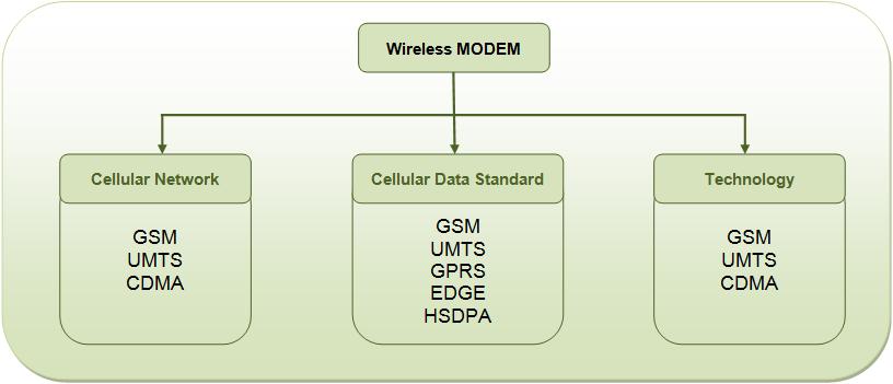
Wireless MODEMs are the MODEM devices that generate, transmit or decode data from a cellular network, for establishing communication between the cellular network and the computer. These are manufactured for specific cellular network (GSM/UMTS/CDMA) or specific cellular data standard (GSM/UMTS/GPRS/EDGE/HSDPA) or technology (GPS/SIM). Wireless MODEMs like other MODEM devices use serial communication to interface with and need Hayes compatible AT commands for communication with the computer (any microprocessor or microcontroller system).

Fig. 2: Flow Chart Showing Classification Of Wireless Modem Based On Network, Data Or Technology
GSM/GPRS MODEM
GSM/GPRS MODEM is a class of wireless MODEM devices that are designed for communication of a computer with the GSM and GPRS network. It requires a SIM (Subscriber Identity Module) card just like mobile phones to activate communication with the network. Also they have IMEI (International Mobile Equipment Identity) number similar to mobile phones for their identification. A GSM/GPRS MODEM can perform the following operations:
1. Receive, send or delete SMS messages in a SIM.
2. Read, add, search phonebook entries of the SIM.
3. Make, Receive, or reject a voice call.
The MODEM needs AT commands, for interacting with processor or controller, which are communicated through serial communication. These commands are sent by the controller/processor. The MODEM sends back a result after it receives a command. Different AT commands supported by the MODEM can be sent by the processor/controller/computer to interact with the GSM and GPRS cellular network.
GSM/GPRS Module
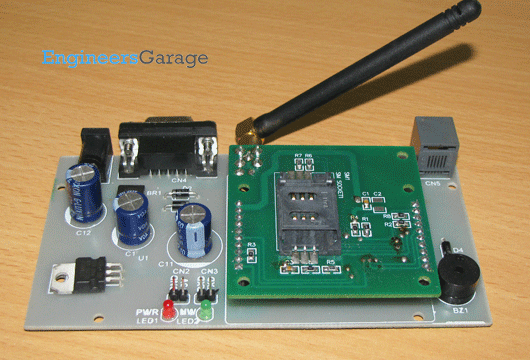
A GSM/GPRS module assembles a GSM/GPRS modem with standard communication interfaces like RS-232 (Serial Port), USB etc., so that it can be easily interfaced with a computer or a microprocessor / microcontroller based system. The power supply circuit is also built in the module that can be activated by using a suitable adaptor.

Fig. 3: An Image of Assembled Circuit For GSM/GPRS Module With Standard Communication Interfaces Like RS-232 Or USB
Mobile Station
Mobile Station (Cell phones and SIM)
A mobile phone and Subscriber Identity Module (SIM) together form a mobile station. It is the user equipment that communicates with the mobile network. A mobile phone comprises of Mobile Termination, Terminal Equipment and Terminal Adapter.

Fig. 4: Block Diagram Showing Diffrent Functions Of Cell Phone And SIM In Mobile Station
Mobile Termination is interfaced with the GSM mobile network and is controlled by a baseband processor. It handles access to SIM, speech encoding and decoding, signaling and other network related tasks. The Terminal Equipment is an application processor that deals with handling operations related to keypad, screen, phone memory and other hardware and software services embedded into the handset. The Terminal Adapter establishes communication between the Terminal Equipment and the Mobile Termination using AT commands. The communication with the network in a GSM/GPRS mobile is carried out by the baseband processor.
Difference between GSM mobile and GSM/GPRS module
A GSM mobile is a complete system in itself with embedded processors that are dedicated to provide an interface between the user and the mobile network. The AT commands are served between the processors of the mobile termination and the terminal equipment. The mobile handset can also be equipped with a USB interface to connect with a computer, but it may or may not support AT commands from the computer or an external processor/controller.
The GSM/GPRS module, on the other hand, always needs a computer or external processor/controller to receive AT commands from. GSM/GPRS module itself does not provide any interface between the user and the network, but the computer to which module is connected is the interface between user and network.
An advantage that GSM/GPRS modules offer is that they support concatenated SMS which may not be supported in some GSM mobile handsets. Also some mobile handsets can’t receive MMS when connected to a computer.
Applications of GSM/GPRS module
The GSM/GPRS module demonstrates the use of AT commands. They can feature all the functionalities of a mobile phone through computer like making and receiving calls, SMS, MMS etc. These are mainly employed for computer based SMS and MMS services.
AT Commands
AT commands are used to control MODEMs. AT is the abbreviation for Attention. These commands come from Hayes commands that were used by the Hayes smart modems. The Hayes commands started with AT to indicate the attention from the MODEM. The dial up and wireless MODEMs (devices that involve machine to machine communication) need AT commands to interact with a computer. These include the Hayes command set as a subset, along with other extended AT commands.
AT commands with a GSM/GPRS MODEM or mobile phone can be used to access following information and services:
1. Information and configuration pertaining to mobile device or MODEM and SIM card.
2. SMS services.
3. MMS services.
4. Fax services.
5. Data and Voice link over mobile network.
The Hayes subset commands are called the basic commands and the commands specific to a GSM network are called extended AT commands.
Command, Information response and Result Codes:
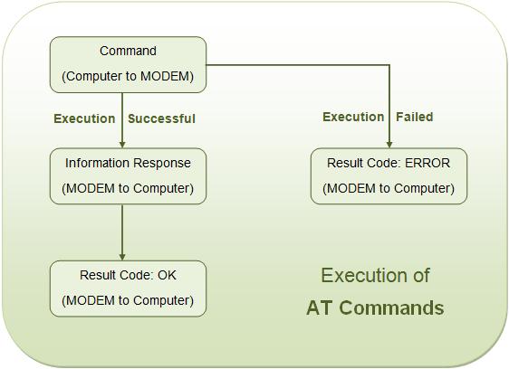
The AT commands are sent by the computer to the MODEM/ mobile phone. The MODEM sends back an Information Response i.e. the information requested by or pertaining to the action initiated by the AT command. This is followed by a Result Code. The result code tells about the successful execution of that command.

Fig. 5: Data Flow Chart Showing Execution Of AT Commands Between PC And Modem
There are also unsolicited Result Codes that are returned automatically by the MODEM to notify the occurrence of an event. For example the reception of a SMS will force MODEM to return an unsolicited result code.
AT Commands’ Syntax
Case Sensitivity –
The AT commands are generally used in uppercase letters. However some MODEMs and mobile phones allow both uppercase and small case letters.
Single Command –
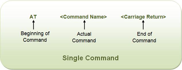
The AT commands include a prefix AT which indicates the beginning of the command to MODEM; and a carriage return which indicates the end of the command.

Fig. 6: Figure Showing Command Format Of Single AT Commands
However string ‘AT’ itself is not the part of the command. For example in ATD, D is the command name not ATD.
The extended AT commands have a ‘+’ in the command name.
For example: AT+CGMI<Carriage return>
Command Line –
Multiple AT commands can be sent to MODEM in a single command line. The commands in a line are separated by a semi-colon (;).

Fig. 7: Figure Showing Format For Sending Mutiple Commands In Single AT
Figure showing Command format of Single AT Commands
For example: AT+CGMI; +CBS<Carriage return>
String in Command Line –
Strings in a command line are enclosed in double quotes.
For example: AT+CGML=”ALL”<Carriage return>
AT Commands continued
Information Response and Result Code –
The Information Response and Result Codes, returned by the MODEM, have a carriage return and line feed in the beginning as well as at the end.

For example:
<Carriage return><Line feed>OK<Carriage return><Line feed>
<Carriage return><Line feed>ERROR<Carriage return><Line feed>
<Carriage return><Line feed>+CBC: 0, 60<Carriage return><Line feed> etc.
Sequence of Execution –
In the command line, the command appearing first is executed first. The execution then follows for second appeared command and so on. The execution of commands in a command line takes place in sequential manner.
If an error occurs in the execution of a command, an error result code is returned by the MODEM and the execution of the command line is terminated irrespective of presence of other commands next in the command line.
Types of commands:
There are four types of AT commands:
1) Test commands
2) Read commands
3) Set commands
4) Execution commands
For more details, see AT Commands.
Different Result Codes:
|
RESULT CODE
|
DESCRIPTION
|
|
OK
|
Successful Execution of a command
|
|
ERROR
|
Execution of a command failed
|
|
+CMS ERROR
|
Message service failure, is returned with an error code
|
|
Unsolicited Result Codes
|
|
|
+CDS
|
Notify receipt of SMS status report of a new message to computer
|
|
+CDSI
|
Notify receipt of SMS status report of a new message and its location in memory to computer
|
|
+CMT
|
Notify forwarding of a new SMS to computer
|
|
+CMTI
|
Notify receipt of SMS status report of a new message and its location in memory to computer
|
Fig. 9: Table Showing Various Results And Description Retured In AT Command
Interfacing Modem
Interfacing MODEM/Mobile phone with Windows platform
The Windows (XP and lower versions) comes with an application called HyperTerminal for data communication through serial port of the computer. The interfacing of the GSM/GPRS module with the serial port of the computer involves following steps:
1) Connect RS-232 port of GSM module with the serial port of the computer. Insert a SIM card in the module.
2) Open HyperTerminal from Start -> All Programs -> Accessories -> Communications -> HyperTerminal.
3) Enter a name for the connection and press OK.
4) Now select the communication port (COM) at which GSM module is connected.
5) Create a new connection set on HyperTerminal. Set parameters, like baud rate as 9600, handshaking mode as none, parity bit as none, stop bit as 1 and data bit as 8.
Filed Under: Articles


Questions related to this article?
👉Ask and discuss on Electro-Tech-Online.com and EDAboard.com forums.
Tell Us What You Think!!
You must be logged in to post a comment.