Electric motors are the most convenient devices in use which can convert the electrical energy into mechanical energy. Electrical motors converts the electrical energy to rotational motion which can then be easily converted to any kind of mechanical motion like moving a robotic arm, moving a needle in a sewing machine etc. The Permanent Magnet Direct Current (PMDC) motors are especially useful since they are very easy to control, produce a lot of power and come in various sizes, shapes and voltage ratings.
When used with electrical or electronic circuits one must be careful about certain things like the current consuming, torque, RPM etc. This article mainly discusses those things and also the details of circuits which can be used to drive the PMDC motors.
1) MOTOR CALCULATIONS
This section is devoted for explaining the most important terms related with a PMDC motor like ‘load’, ‘torque’, ‘RPM’ etc. The capability of a PMDC motor is usually mentioned in terms of torque and RPM.
A) LOAD or MOMENT OF INERTIA
Every mass in the universe possess inertia. Inertia is the resistance of a body against its change of position, speed etc. The rotating bodies also possess a kind of inertia called moment of inertia. The moment of inertia can be considered as the rotational load or the mass equivalent in linear motion. In case of a robotic arm the rotational load is the sum of frictional force, weight of the arm etc.
Load or moment of inertia is equal to the amount of rotational force that should be applied to just start rotating a body which was at rest
B) TORQUE & CURRENT
Torque of a motor is the rotational force which it should generate so as to accelerate a Load attached to its shaft to a required rotating speed.
In the case of a motor the rotating body could be anything like a robotic arm, wheels of a toy car etc. If the motor is running with the rotating body at the required speed then it can be said that the motor is generating enough torque as required.The relation between the torque and the load is shown in the following equation;
TORQUE = LOAD * ANGULAR ACCELERATION
If the torque is represented by ‘T’, the load is represented by ‘L’ and the angular acceleration as ‘A’, then the above equation cab be re-written as
T = L * A
When a motor accelerates a load ‘L’ from 0 RPM to a constant RPM within ‘t’seconds, then the torque generated can be found as

Torque is actually a kind of force whose value increases as the distance from the center of rotation increases. Consider the below figure in which a rolling wheel is shown which is driven by a motor.
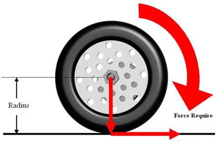
Fig. 1: Image showing Concept of Torque of a Wheel
The radius of a wheel is marked in the figure and the force required to rotate it is also marked in red. This wheel has its own weight and there might be weight of a vehicle adding to that if the wheel is attached to one. Now the torque required to rotate the wheel can be calculated using the following relation,
T = FD
Where;
T is the torque required,
F is the amount of force that should be applied and
D is the distance from the center of the shaft to the point where the torque is measured, in the case of a wheel like the one shown in the above figure the distance is the radius of the wheel itself.
Hence simply by increasing the diameter of the wheel the torque can be increased.The unit of the torque is Newton Meter (Nm)
Thetorque ‘T’ which a dc motor generates to rotate a body and the current ‘I’ consuming at the same time has a linear relationship. The value of the torque and the current consuming is always proportional to each other and the proportionality constant is called the torque constant KT.
T = KT * I
The value of the KTmight be available in the datasheet of a DC motor or else it can be calculated from the value of other parameter given in the datasheet like NOMINAL TORQUE and NOMINAL CURRENT, which are actually the normal values of torque and current at which the motor is supposed to operate.
The torque constant can be calculated as;
KT = NOMINAL TORQUE / NOMINAL CURRENT
Once the value of the KT is found then the torque generated by the motor while it is running at any value of current can be calculated by using the relation T = KT* I. The following arrangement shows how it is possible to calculate the torque generated by a motor using a simple multi-meter;
If a wheel is used as the rotating body then the simplest way to vary the torque requirement is to increase the mass of the rotating body by increase the number of wheels attached to the shaft. More the number of wheels more is the requirement of the torque and the motor should generate that much torque
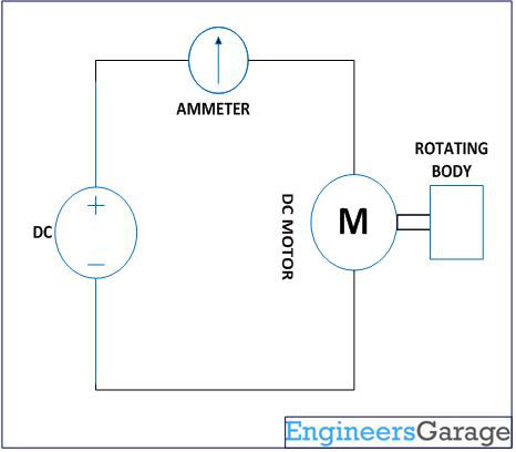
Fig. 2: Circuit Diagram of PMDC Motor driver
RATED VOLTAGE in the datasheet of the motor. The RATED VOLTAGE is the voltage at which the motor is designed to operate and all the values of the datasheet have been measured at the same voltage.
In the circuit an ordinary multi-meter can be used in power measuring mode as an ammeter which will display the value of current consumed by the motor at different loads.
Suppose if the value of the KT has been calculated from the datasheet using the relation
KT= NOMINAL TORQUE / NOMINAL CURRENTas 0.003 and the current consuming by the motor while running at the RATED VOLTAGEwith an unknown load is 10mA, the torque generated by the motor can be calculated as follows
T = 0.003 * 0.01 = 0.03 mNm
C) RPM &VOLTAGE
The speed of a motor is usually mentioned in terms of RPM (Rotationsper Minute). There is a relation between the RPM, voltage applied and the current consuming for a particular motor.
Consider the following figure in which the internal equivalent circuit of the motor running at a DC supply of ‘V’ is shown;
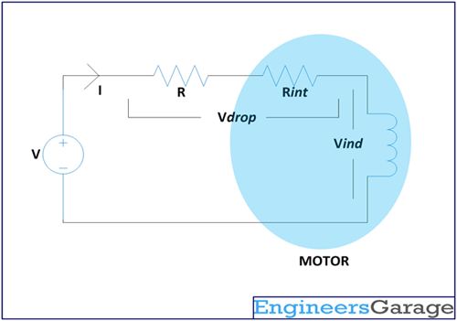
Fig. 3: Equivalent Circuit Diagram of PMDC Motor
The internal armature of a motor can be viewed as having an ideal coil with an ideal series resistance. They are mentioned ideal since the coil is purely inductive and should not introduce any resistance into the circuit. The internal resistance is purely resistive and should not introduce any inductance into the circuit. In the circuit shown above the internal resistance is marked as ‘Rint’ and the voltage induced across the internal inductance is ‘Vind’. This is the equivalent of the motor armature or winding coil.
Vind = V – Vdrop
Now the significance of this circuit is that the speed of the motor depends purely on the voltage ‘Vind’ and the torque generated at that voltage depends purely on the value of current ‘I’ flowing through circuit.
It is already discussed previously that the torque is always proportional to the current flowing through the circuit by a proportionality constant KT. Similarly the speed and the voltage induced ‘Vind’ is also proportional to each other by the same constant.
Vind = KE * S
Where;
Vind is the induced voltage in the coil
S is the speed in the unit of radians/seconds
KE is the voltage constant which has the same value as KT
From the above equation the speed in RPM can be calculated as

Since the Vind can’t be measure directly since in real the ‘Rint’ and the coil together forms the winding coil of the armature. Since the same current ‘I’ flows through the resistance and the coil the following equation is more useful in finding the speed in RPM with respect to the applied voltage ‘V’.

The ‘V’ is the constant DC voltage supplied, the Rint is a constant which might be given in the datasheet as COIL RESISTANCE or can be measure using a multi-meter, ‘KE‘which is same as ‘KT‘ can be calculated as discussed in the previous section and the ‘R’ is a known value of resistance.The following circuit can be used to do the calculate the speed of a motor at different torquerequirement and at different values of ‘R’;
Fig. 4: Equivalent Circuit Diagram of PMDC Motor
It can be found that as the torque requirement increases the current ‘I’ increases. Hence for a particular value of current ‘I’, using the previous equation for calculating speed;
RPM = ( V – I ( R + Rint ) ) * 60 / ( 2? * KE )
The RPM decreases as the value of ‘R’ increases and as the value of ‘R’ decreases the RPM increases. Hence using the above circuit the RPM for a motor running with a load can be adjusted.
D) POWER
The power is the capability of a motor to keep on rotating a Load at a particular speed
The power is defined as the product of the torque and the speed. If the speed is calculated in RPM the the power is given by the equation

Where;
P is the power calculated
T is the torque generated
RPM is the speed of the motor
Summary:
· Load or moment of inertia is equal to the just enough amount of rotational force that should be applied to start rotating a body which was at rest
· Torque of a motor is the rotational force which it should generate so as to accelerate a Load attached to its shaft to a required rotating speed
When a motor accelerates a load ‘L’ from 0 RPM to a constant RPM within ‘t’ seconds, then the torque generated can be found as

· The torque generated by a motor depends only on the current flowing through the motor. As the demand for the torque increases the current flow increases as per the equation
T = KT * I
· The speed of a motor depends only on the voltage induced across the coil

· As the current increases due to the torque the RPM decreases as per the equation

· The power is the capability of a motor to keep on rotating a Load at a particular speed

Datasheet Specifications
2) DATASHEET SPECIFICATIONS
All the details required for the proper operation with a PMDC motor is specified in its datasheet itself and there won’t be any trouble using the motors if one takes care of those specifications. This particular section explains the PMDC motor specifications in the simplest possible way.
Consider the following figure in which is the performance graph of a 5V PMDC motor from PRECISION MOTOR DRIVES, model no. 116-101.
Fig. 5: Typical Image of a DC motor
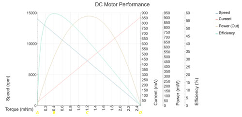
Fig. 6: Graph showing Electrical Parameters of a DC Motor
It looks very complex but this single figure has all the required details. The following section reads the graph and explains the significant things for a designer. Please note the points A, B, C and D which are the points along the increasing order of torque.
A) Motor started and running at no Load
The motor is just being started and is running without any Load. The voltage that should be applied at any stage of a PMDC motor should be the RATED VOLTAGE.
The terms in bold font are the specifications one can find in a datasheet.
Torque = 0mNm
Voltage applied = RATED VOLTAGE = 5V
Efficiency calculated = 0%
Output calculated = 0mW
Speed generated = NO LOAD SPEED = 14000rpm
Current consumed = NO LOAD CURRENT = 40mA
B) Motor running at maximum efficiency
The motor is now rotating a Load at a speed and hence generating a torque. At this particular torque and speed motor runs with maximum efficiency. Here motor has to consume more current than before but the speed decreases.
Torque =TORQUE AT MAXIMUM EFFICIENCY = 0.4mNm
Efficiency calculated = MAXIMUM EFFICIENCY = 60%
Output calculated = POWER AT MAXIMUM EFFICIENCY = 500mW
Speed reduces to a speed = SPEED AT MAXIMUM EFFICIENCY = 11500rpm
Current consumption increases to a current = CURRENT AT MAXIMUM EFFICIENCY = 150mA
C) Motor running at maximum power
The motor is now running with larger Load than before and hence generating more torque, but the speed is less speed compared to previous case. At this point the product of torque and speed will give the maximum value for power and hence it is said to be running at maximum power.
Torque = TORQUE AT MAXIMUM POWER = 1.2mNm
Efficiency calculated = EFFICIENCY AT MAXIMUM POWER= 40%
Output calculated = MAXIMUM POWER = 900mW
Speed reduces to a speed = SPEED AT MAXIMUM POWER = 7000rpm
Current consumption increases to a current = CURRENT AT MAXIMUM POWER = 450ma
D) Motor not running due to heavy Load
Again if the Load applied is increased the motor won’t be able generate enough torque to rotate it. Hence the speed reduces and finally the motor will come to a stop. At this point the maximum current will be consumed but without any rotation.
Torque = STALL TORQUE >= 2.5mNm
Efficiency calculated = 0%
Output calculated = 0mW
Speed reduces to a speed = 0rpm
Current consumption increases to a current = STALL CURRENT = 850mA
The reading from the performance graph can be summarized as follows;
For a DC motor running with a constant voltage, the speed decreases and the current consumption increases with the increase in the heaviness of the Load applied on to it. Dependingupon load the motor can run with maximum speed, maximum efficiency, maximum power or even not running.
How to select a PMDC Motor
3) HOW TO SELECT A PMDC MOTOR
If a PMDC motor need to be connected with a circuit, take care of the following things;
– The circuit should be able to provide the required RATED VOLTAGEof the motor
– The required torque that the motor has to generate should be in between values for TORQUE AT MAXIMUM EFFICIENCY and TORQUE AT MAXIMUM POWER, so that the motor runs in between regions of MAXIMUM EFFICIENCYand MAXIMUM POWER.
– The circuit can at least source a current more than CURRENT AT MAXIMUM POWER
– The circuit should be designed in such a way that it won’t get damaged even if a current equal to STALL CURRENT flows through the circuit
4) HOW TO DESIGN A PMDC MOTOR CIRCUIT FOR AN UNKNOWN LOAD
This particular section explains the steps required to design a PMDC motor circuit when a rotating body of unknown Load is required to rotate at a specified RPM.
A) CALCULATE THE LOAD
Rotate the given body with any motor having enough power and known TORQUE CONSTANT( KT) as shown in the following figure for calculating the Load.
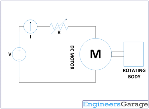
Fig. 7: Equivalent Circuit Diagram of PMDC Motor
When the motor is started it consumes a very large current and as the speed increases the current falls to a steady value. Start the motor and measure the time ‘t’ taken by the motor till the current it consume become steady. Now read the value of current displayed in the ammeter.
The torque generated by the motor, T = KT * I
The RPM can be calculated as,

The Load can then be calculated from the equation of torque,

The Load,

B) CALCULATE THE TORQUE REQUIRED
The value of the Load has been calculated and now the torque required to accelerate that Load from rest to a specified RPM can be calculated using the following equation of torque.
The torque required,

C) CALCULATE THE POWER REQUIRE
The power required by a motor to generate that much torque at the specified RPM can be calculated using the following equation of power;
The power required,

D) SELECT THE MOTOR
When the value of power required has been calculated, a motor that has the same value of power in the region between MAXIMUM EFFICIENCY and MAXIMUM POWER can be selected for the design.
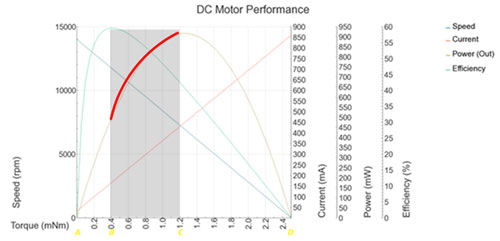
Fig. 8: Graph showing Maximum Power Curve of PMDC Motor
E) CALCULATE THE CURRENT
Once the motor has been selected, go through its datasheet and find the value of its TORQUE CONSTANT( KT ). With the help of that value the current consumed by that motor at that particular torque can be found out using the torque equation, T = KT * I
The current that the motor will consume, I = KT / T
F) CALCULATE THE INDUCED VOLTAGE
The voltage that should be induced at the coil of the motor when it is running at the specified RPM
can be calculated from the equation of RPM,

The voltage that will be induced at the specified RPM, Vind

G) DESIGN THE VALUE OF SERIES RESISTANCE
Suppose the circuit that need to be designed is the one which is given in the following figure, connect the selected motor with known INTERNAL RESISTANCE( Rint ) as shown.

Fig. 9: Equivalent Circuit Diagram of PMDC Motor
Suppose ‘Vr’ is the voltage across the resistance whose value need to be calculated and the ‘Vrint’ is the voltage across the know resistance ‘Rint’. Since the value of ‘Vind’, ‘I’ are already calculated and the value of supply voltage ‘V’ is known, the value of ‘R’ can be calculated using the following equation;
The series resistance, R = ( V – I * Rint – Vind) / I
This completes the design of a PMDC motor circuit which is required to rotate an unknown Load at a specified RPM
How to Provide Enough Current
5) HOW TO PROVIDE ENOUGH CURRENT
As mentioned above the motor driving circuit should be able to provide a current more than CURRENT AT MAXIMUM POWER. Hence specialized switching circuits are required which can source large enough current to the motor. The details of most commonly found motor driving ICs are discussed below;
A) ULN200x
The ULN2002, ULN2003, ULN2004 etc. are Darlington pair based ICs which can source large enough current. These ICs can source a maximum of 500mA per each output. They can operate up to 50V.Each IC has seven outputs which are powered by seven different Darlington pairs. The pin out of the IC is shown in the following figure;
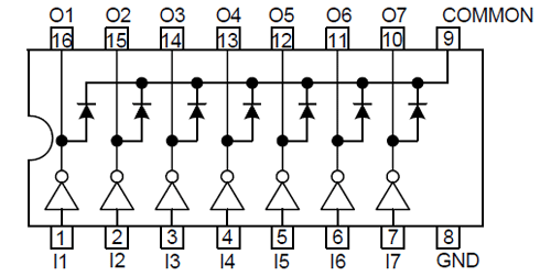
Fig. 10: Pin Diagram of ULN200x IC
When working with ICs always keep one thing in the mind that their outputs are ‘open-drain’. The collector of two NPN transistors of a Darlington pair is shorted together and ismade available at the output pin.
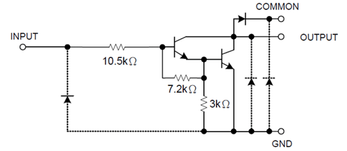
Fig. 11: Circuit Diagram of Darlington pair
Since the NPN transistors will work only when it is connected to the positive supply, the outputs current will flow through the load at a pin only when the other end of the load is connected to the positive supply.
The PMDC motor will work with the ULN200x only when one lead of the motor is connected to the output pin and the other lead to the positive supply
The current always flows in one direction through the coil of the PMDC motor when it is driven using ULN200x IC and hence the direction of rotation will be always same.
Once connected with ULN200x IC the PMDC motor can be rotated in one direction only
The following figure shows an example of a motor driven using ULN200x, where the motor is connected between one of the outputs and the positive supply.
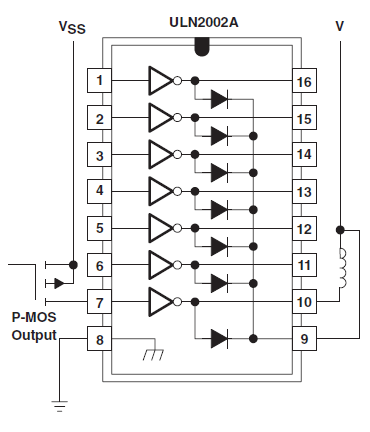
Fig. 12: Circuit Diagram of ULN2002A based DC Motor Driver
B) L293D
Unlike the previously discussed ULN200x ICs, the L293 and L293D ICs can drive a PMDC motor in both directions. This IC can source slightly more current than the ULN200x as its maximum current per output pin is 600mA. When output is generated as pulses, this IC can deliver 2A maximum if the pulse width is less than 5 micro seconds. Another advantage of this IC compared to the ULN200x is that it has an enable pin for each pair of output.
The pin out of the L293D is shown in the following figure;
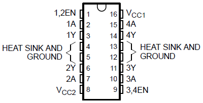
Fig. 13: Pin Diagram of L293D Motor Driver IC
The logic diagram in the following figure shows the output pairs which can be controlled using single enable pins.
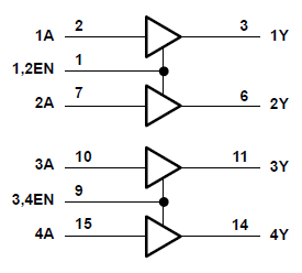
Fig. 14: Logic Diagram showing Output Pairs Controlled by Single Enable Pin
Unlike ULN200x which use only a single Darlington pair for each output, the L293D uses two Darlington pair in a push-pull manner so that it can source current in both directions. The internal circuitry of the L293D for a single output pin is shown in the following figure;
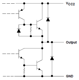
Fig. 15: Circuit Diagram of Darlington Pair Inside Motor Driver IC
The advantage of such an arrangement is that the motor need not to be always connected to the positive supply. If one lead of the PMDC motor is connected to the output pin, then the other lead can be connected to positive, ground or even to another output pin.
The following figure shows three motors connected to a L293D IC of which the one connected between two output pins can rotate in both directions according to the voltage at the enable pin while the others can rotate in one direction only.
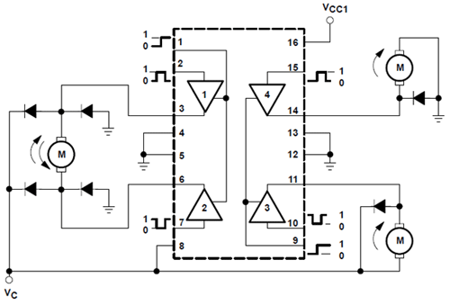
Fig. 16: Circuit Diagram of L293D IC based DC Motor Driver
The Vcc1 and Vc are two separate positive supply for the circuit and the diodes are connected in reverse biased direction to check the back emf generated at the motor coils due to switching.
Need for Protection Circuits
6) NEED FOR PROTECTION CIRCUITS
If the circuit can provide the rated voltage and enough current to run the motor for a load applied, the motor will run without any problem. However the motor while running can cause problems in the circuits and in turn it can affect its own working. A motor can cause problems in a circuit in the following ways.
– It can produce back emf which can damage the components
– The brush contacts can produce low frequency noise
– The current flowing through the coil can produce RF noise
The back emf is the voltage produced in the coil in the backward direction normally occurs at the time of motor switching on or off. The back emf produced in a motor can be checked by applying a reverse biased diode across the terminals of the coil so that whenever the back emf occurs the reverse biased diode will conduct and short circuit it before it can affect other components.
The brushes inside a motor continuously make and break contact with the coil windings while running. This sudden make and break process will cause voltage to suddenly fall and rise across the terminals for a very short time. This appears as a low frequency noise across and can be prevented by applying a large enough polarized capacitor across the terminals.
Whenever a current flows through a coil RF frequencies are generated and it will happen when the current flows through the coils of the motor also. Here these RF frequencies are unwanted and can cause problems in the circuit itself or in nearby electronic instruments like TV, radio etc. To prevent this unwanted RF frequencies, use a decoupling capacitor of very small value across each leads of the motor and the ground so that the RF noise will get shorted to the ground through the capacitor.
An example for the protection circuit that can be applied across the terminals of a motor is shown in the following figure;
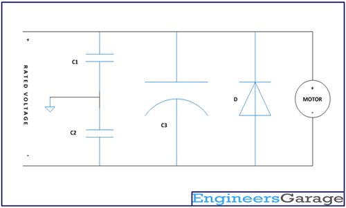
Fig. 17: Circuit Diagram of DC Motor Protection
In the above circuit the C1 and C2 are the capacitors used for removing RF noise and the C3 is the capacitor used to remove low frequency noise and the D is the diode used for short circuiting the back emf. Please note that for this particular circuit the voltage polarity for each terminal is fixed and hence the motor will rotate in one direction only. The range of values for the components which can be used is given below;
C1 = 0.01uF to 0.1uF
C2 = 0.01uF to 0.1uF
C3 = 10uF to 100uF
D = 1N4007
Filed Under: Tutorials


Questions related to this article?
👉Ask and discuss on EDAboard.com and Electro-Tech-Online.com forums.
Tell Us What You Think!!
You must be logged in to post a comment.