Engineers Garage

  • Projects and Tutorials
    • Electronic Projects
      • 8051
      • Arduino
      • ARM
      • AVR
      • PIC
      • Raspberry pi
      • STM32
    • Tutorials
    • Circuit Design
    • Project Videos
    • Components
  • Articles
    • Tech Articles
    • Insight
    • Invention Stories
    • How to
    • What Is
  • News
    • Electronic Products News
    • DIY Reviews
    • Guest Post
  • Forums
    • EDABoard.com
    • Electro-Tech-Online
    • EG Forum Archive
  • Digi-Key Store
    • Cables, Wires
    • Connectors, Interconnect
    • Discrete
    • Electromechanical
    • Embedded Computers
    • Enclosures, Hardware, Office
    • Integrated Circuits (ICs)
    • Isolators
    • LED/Optoelectronics
    • Passive
    • Power, Circuit Protection
    • Programmers
    • RF, Wireless
    • Semiconductors
    • Sensors, Transducers
    • Test Products
    • Tools
  • EE Resources
    • DesignFast
    • LEAP Awards
    • Oscilloscope Product Finder
    • White Papers
    • Webinars
  • EE Learning Center
    • Design Guides
      • WiFi & the IOT Design Guide
      • Microcontrollers Design Guide
      • State of the Art Inductors Design Guide
  • Women in Engineering

Circuit Design: Heat sensor circuit diagram

By Anjali Sethiya


Heat sensor senses the heat present around the sensor. When temperature rises above the set value, it will indicate the presence with the help of glowing LED. This heat sensor circuit can be used in kitchen or inside your PC. If your kitchen appliances or PC are over heated, it may be possible that it will damage the expensive components present in it. So to protect them from damage we have described a simple circuit which will give an indication when temperature around the sensor increases above the level set by you. This circuit is very small and can be easily install. In short, this simple project with easy to build electronic circuit is very useful to fight with problems like overheating.

The circuit is based on two IC and few more discrete components namely-

1. LM35 – LM35 is a precision integrated circuit temperature and its output voltage is linearly proportional to centigrade temperature. LM35 detects the surrounding temperature and according to reference value set it which will give you the output. When output voltage is multiplied by 100 it will give you the temperature sensed in degrees. So you can easily set your reference voltage. Pin configuration of LM35 IC is shown below.
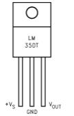
LM35

 Feature of LM35 IC

•  It directly gives output temperature in degree Celsius so there is no need for conversion of temperature.

•  Operating temperature range varies from -55 to +150 degrees.

•  LM35 is also suitable for remote application.

•  Operating voltage range varies from 4 to 30 volts.

•  It draws only 60 µA from power supply; therefore it has very low self heating.

•  It comes in sealed package (plastic covering) therefore problem of oxidation of IC does not happen.


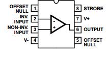
2. CA3130 – IC CA3130 is operational amplifier which combines the advantage of both CMOS and bipolar transistor on a single chip. Operating voltage range varies from 5V to 16V. CA3130 has advantage that they can be phased compensated with a single external capacitor and have terminals for adjustment of offset voltage. In this you can adjust the reference voltage at inverting and non -inverting pin so that when voltage at inverting pin is more than non-inverting pin. It will make the out pin high and vice versa. Pin configuration of CA3130 IC is shown below.

CA3130

3. LED – LED stands for light emitting diode. It is made up of semiconductor device which emit different light source as its output. LED is a semiconductor diode that emits narrow-spectrum light when electrically biased in the forward direction of the p-n junctions; When LED is switched ON, electronics combines with hole and the device release energy in the form of light. LED are Available in Red, Orange, Amber, Yellow, Green, Blue and White.  Now a day’s LED’s are available in visible, ultraviolet and infrared wavelengths and have high brightness.

4. Resistor – Resistor is a two terminal passive component used to control the flow of current into the circuit. A current through resistor is directly proportional to the voltage applied across resistor terminal.

Resistor comes in two varieties –  

1. Fixed resistor means they have fixed value of resistance.

2. Variable resistors means there value can be changed like if you have variable resistor of 5K then you can vary the resistance from 0 to 5 K Ohms.

We can calculate the value of resistor with the help of multi-meter or we can do it with help of color code available on resistor.

5. Capacitor – A capacitor is a two terminal passive component which stores electric charge. Capacitor consists of two conductors which are separated by a dielectric medium. It works when potential difference applied across the conductors polarizes the dipole ions to store the charge in the dielectric medium.

 Capacitor comes in two varieties-

1. Polarised capacitor- They have polarity means + and – sign. They are basically used to store charge. As they store charge they should be carefully discharge before troubleshooting the circuit.

2. Non polarized capacitor – They do not have polarity and can be mounted any way. They are basically used to remove the fluctuation present in conversion of AC to DC.

Working of circuit

Working of heat sensor circuit

In this circuit we have set the fix voltage at inverting pin that is at pin 2 of IC2 and non inverting pin 3 of IC2 is connected with the output pin 2 of IC1 through a resistor.  Initially we have to do some hit and trial method to set the temperature with the help of variable resistor VR1. VR1 provides a reference voltage that can be set anywhere from 0V to approx. 1V. In our circuit we have set a 0.71V approx at pin 2 which means when temperature reaches above 71 degree Celsius it will give you an indicator with the help of LED. Now when temperature at IC1 increases because of heat from kitchen appliances or PC voltage at pin 2, IC1 also increases which increase the voltage at pin 3 of IC2 and when voltage become more than 0.71 V it will make the output pin 6 high and LED connected to it start blinking. When temperature reaches below the set value, LED stop blinking indicating your device is safe.   
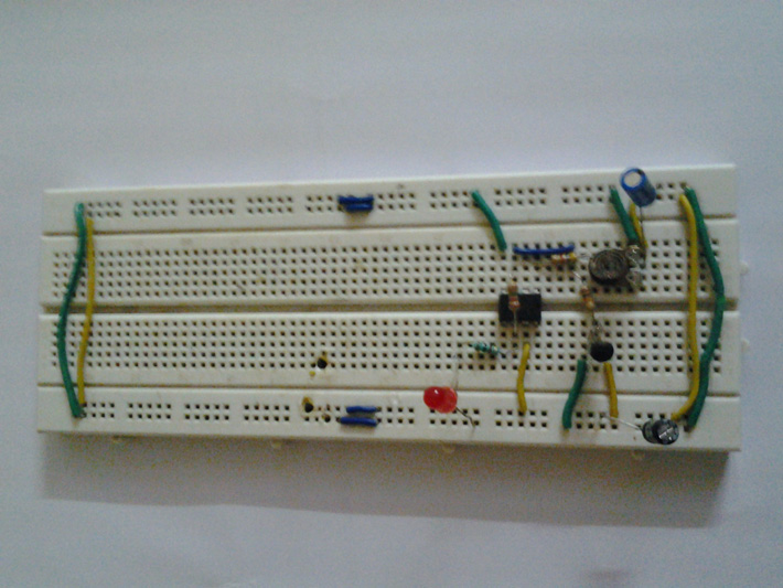
Heat Sensor


Circuit Diagrams

Heat-sensor-

Project Video


Filed Under: Circuit Design
Tagged With: heat sensor
 

Questions related to this article?
👉Ask and discuss on EDAboard.com and Electro-Tech-Online.com forums.


Tell Us What You Think!! Cancel reply

You must be logged in to post a comment.

HAVE A QUESTION?

Have a technical question about an article or other engineering questions? Check out our engineering forums EDABoard.com and Electro-Tech-Online.com where you can get those questions asked and answered by your peers!


Featured Tutorials

  • Introduction to Brain Waves & its Types (Part 1/13)
  • Understanding NeuroSky EEG Chip in Detail (Part 2/13)
  • Performing Experiments with Brainwaves (Part 3/13)
  • Amplification of EEG Signal and Interfacing with Arduino (Part 4/13)
  • Controlling Led brightness using Meditation and attention level (Part 5/13)
  • Control Motor’s Speed using Meditation and Attention Level of Brain (Part 6/13)

Stay Up To Date

Newsletter Signup

Sign up and receive our weekly newsletter for latest Tech articles, Electronics Projects, Tutorial series and other insightful tech content.

EE Training Center Classrooms

EE Classrooms

Recent Articles

  • EdgeLock A5000 Secure Authenticator
  • How to interface a DS18B20 temperature sensor with MicroPython’s Onewire driver
  • Introduction to Brain Waves & its Types (Part 1/13)
  • An Embedded Developer’s Perspective on IOT (Internet of Things)
  • Understanding NeuroSky EEG Chip in Detail (Part 2/13)

Most Popular

5G 555 timer circuit 8051 ai Arduino atmega16 automotive avr bluetooth dc motor display Electronic Part Electronic Parts Fujitsu ic infineontechnologies integratedcircuit Intel IoT ir lcd led maximintegratedproducts microchip microchiptechnology Microchip Technology microcontroller microcontrollers mosfet motor powermanagement Raspberry Pi remote renesaselectronics renesaselectronicscorporation Research samsung semiconductor sensor software STMicroelectronics switch Technology vishayintertechnology wireless

RSS EDABOARD.com Discussions

  • Pic 16f877A Hex file
  • finding attenuation coefficient in CST
  • 7 segment display connections
  • Effect of variable gain amplifier and LNA on the input RF signal's phase
  • HF preamplifier with threshold?

RSS Electro-Tech-Online.com Discussions

  • I've DESTROYED 3 piezo buttons :((((
  • led doorbell switch
  • RF modules which can handle high number of bytes per second
  • How does a NOAC work?
  • intro to PI
Engineers Garage
  • Analog IC TIps
  • Connector Tips
  • DesignFast
  • EDABoard Forums
  • EE World Online
  • Electro-Tech-Online Forums
  • Microcontroller Tips
  • Power Electronic Tips
  • Sensor Tips
  • Test and Measurement Tips
  • 5G Technology World
  • About Us
  • Contact Us
  • Advertise

Copyright © 2022 WTWH Media LLC. All Rights Reserved. The material on this site may not be reproduced, distributed, transmitted, cached or otherwise used, except with the prior written permission of WTWH Media
Privacy Policy | Advertising | About Us

Search Engineers Garage

  • Projects and Tutorials
    • Electronic Projects
      • 8051
      • Arduino
      • ARM
      • AVR
      • PIC
      • Raspberry pi
      • STM32
    • Tutorials
    • Circuit Design
    • Project Videos
    • Components
  • Articles
    • Tech Articles
    • Insight
    • Invention Stories
    • How to
    • What Is
  • News
    • Electronic Products News
    • DIY Reviews
    • Guest Post
  • Forums
    • EDABoard.com
    • Electro-Tech-Online
    • EG Forum Archive
  • Digi-Key Store
    • Cables, Wires
    • Connectors, Interconnect
    • Discrete
    • Electromechanical
    • Embedded Computers
    • Enclosures, Hardware, Office
    • Integrated Circuits (ICs)
    • Isolators
    • LED/Optoelectronics
    • Passive
    • Power, Circuit Protection
    • Programmers
    • RF, Wireless
    • Semiconductors
    • Sensors, Transducers
    • Test Products
    • Tools
  • EE Resources
    • DesignFast
    • LEAP Awards
    • Oscilloscope Product Finder
    • White Papers
    • Webinars
  • EE Learning Center
    • Design Guides
      • WiFi & the IOT Design Guide
      • Microcontrollers Design Guide
      • State of the Art Inductors Design Guide
  • Women in Engineering