TThis simple circuit will act as a warning alarm whenever the temperature of a device exceeds above the safety level. This circuit can be used to monitor the heat built inside the devices like your PC, inverters, CD player etc. As excessive heat may affect the sensitive component and may lead to permanent damage. The main advantage of this circuit is its compactness that's why it can be easily install in the device itself. This circuit will also give you power on indicator of a device with the help of blinking LED. Therefore it attract your attention that device is on. This circuit uses a negative temperature coefficient (NTC) as a sensor to sense the heat. This circuit can be operated on wide range of temperature vary from 5V to 12V.
· This simple heat sensor circuit will act as a warning alarm whenever the temperature of a device exceeds above the safety level.
· This circuit can be used to monitor the heat built inside the devices like your PC, inverters, CD player etc. As excessive heat may affect the sensitive component and may lead to permanent damage.
· The main advantage of this circuit is its compactness that’s why it can be easily install in the device itself.
· This circuit will also give you power on indicator of a device with the help of blinking LED. Therefore it attract your attention that device is on.
· This circuit uses a negative temperature coefficient (NTC) as a sensor to sense the heat.
· This circuit can be operated on wide range of temperature vary from 5V to 12V.
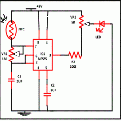
Heat sensor using thermister is based on a commonly known IC NE555 timer wired in astable mode. The frequency of oscillation of NE55 timer depends upon resistor R1 (NTC), variable resistor VR1 and capacitor C1. Charging and discharging time of capacitor lies between 1/2 and 2/3 of Vcc.
And a thermister is a special kind of resistor whose resistance depends upon the temperature around it. The resistance of NTC thermister decreases to few ohms when temperature around it increases. And we are utilizing this phenomenon.
In normal condition at room temperature LED fleshes at the rate of 1Hz. And frequency of oscillation can be set with the help of VR1. If LED is fleshing continuously with same rate than temperature inside device is in safe limit. As soon as temperature inside the device rises because of microprocessor fan stop working or maybe you are using your device for long period or because of any other reason. When temperature around the thermister rises, due to heat built around sensor resistance of thermister decreases. Because of this fleshing rate of LED also decreases. This will now give you an indicator that temperature inside the device is crossing the safe limit.
And a time come when LED stop fleshing which indicate that danger level has reached and it’s time to off the device so that it become cool. And you can prevent your device from damage.
Before mounting the negative temperature coefficient thermister first check it at room temperature it resistance should vary between 400 to 500 ohms.

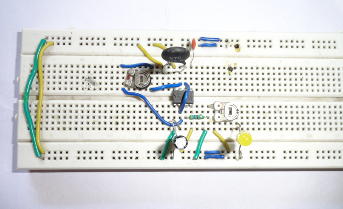
Fig. 1: Prototype of 555 IC and Thermister based Ambient Heat Sensor
Circuit Diagrams
Project Components
Filed Under: Electronic Projects


Questions related to this article?
👉Ask and discuss on Electro-Tech-Online.com and EDAboard.com forums.
Tell Us What You Think!!
You must be logged in to post a comment.