Engineers Garage

  • Electronic Projects & Tutorials
    • Electronic Projects
      • Arduino Projects
      • AVR
      • Raspberry pi
      • ESP8266
      • BeagleBone
      • 8051 Microcontroller
      • ARM
      • PIC Microcontroller
      • STM32
    • Tutorials
      • Audio Electronics
      • Battery Management
      • Brainwave
      • Electric Vehicles
      • EMI/EMC/RFI
      • Hardware Filters
      • IoT tutorials
      • Power Tutorials
      • Python
      • Sensors
      • USB
      • VHDL
    • Circuit Design
    • Project Videos
    • Components
  • Articles
    • Tech Articles
    • Insight
    • Invention Stories
    • How to
    • What Is
  • News
    • Electronic Product News
    • Business News
    • Company/Start-up News
    • DIY Reviews
    • Guest Post
  • Forums
    • EDABoard.com
    • Electro-Tech-Online
    • EG Forum Archive
  • DigiKey Store
    • Cables, Wires
    • Connectors, Interconnect
    • Discrete
    • Electromechanical
    • Embedded Computers
    • Enclosures, Hardware, Office
    • Integrated Circuits (ICs)
    • Isolators
    • LED/Optoelectronics
    • Passive
    • Power, Circuit Protection
    • Programmers
    • RF, Wireless
    • Semiconductors
    • Sensors, Transducers
    • Test Products
    • Tools
  • Learn
    • eBooks/Tech Tips
    • Design Guides
    • Learning Center
    • Tech Toolboxes
    • Webinars & Digital Events
  • Resources
    • Digital Issues
    • EE Training Days
    • LEAP Awards
    • Podcasts
    • Webinars / Digital Events
    • White Papers
    • Engineering Diversity & Inclusion
    • DesignFast
  • Guest Post Guidelines
  • Advertise
  • Subscribe

Hi-tech Laser based Intruder Detector

By Ganesh Selvaraj January 15, 2015


This tutorial will show you how to make a Laser based Intruder alerter which captures image of the intruder automatically without any microcontroller or programming.

Components Required:

1. Laser pointer
 
2. 10 or more mirror pieces (minimum dimensions: 1” X 1”)
 
3. Light Dependent Resistor
 
4. LM741 IC
 
5. 10k Potentiometer
 
6. LED + 330 ohms resistor
 
7. A Canon camera (or any digital camera with USB remote)
 
8. USB cable


What is so Hi-tech about this?

You may have seen a few movies where there is a security system containing multiple laser rays flashing across the room which, when interrupted, triggers an alarm. We are going to try replicating that kind of arrangement using a single laser pointer and a couple of mirrors.


Setup instructions

– First, we need to do some modification to the LASER pointer. Remove the batteries and tape the tactile switch in such a way that it  always remains ON. Now place back the batteries and see if you taped the switch properly.
 

Image of Laser Pointer with Batteries removed

Fig. 1: Image of Laser Pointer with Batteries removed

Image of Laser Pointer showing its tactile switch tapped to remain ON permanently

Fig. 2: Image of Laser Pointer showing its tactile switch tapped to remain ON permanently

Image of Laser Pointer pointing Laser Light to a Target

Fig. 3: Image of Laser Pointer pointing Laser Light to a Target

– Now attach (solder/tape/glue) two wires to the laser, one to the positive terminal and another to the negative. We are doing this since the laser would be kept ON continuously and batteries run out pretty soon.
 
– Next, assemble the circuit on a breadboard as per the circuit diagram. For now, I only connected an LED to the output.
 
– Now adjust (by rotating the Potentiometer screw) the threshold value such that the LED connected to output glows when the laser ray is not pointed towards the LDR. When the light falls on the LDR, the output must become low (output LED should turn OFF)

Prototype of LM741 OPAMP IC based Circuit used for detection of Laser Light

Fig. 4: Prototype of LM741 OPAMP IC based Circuit used for detection of Laser Light

Image showing Laser Pointer connected with LM741 IC based Intruder Detector

Fig. 5: Image showing Laser Pointer connected with LM741 IC based Intruder Detector

Now, Lets modify our camera to enable USB remote triggering.

Note:

1. The hack mentioned below only works with canon cameras.
 
2. Skip this step if your camera already has a USB remote feature.

Page-2

Now you have to install a program called CHDK (Canon Hack Development Kit) in your canon camera. Don’t worry! The procedure is temporary and doesn’t modify your camera’s ROM.

Here is a video by BigNate84 showing how to install CHDK: https://www.youtube.com/watch?v=HYOaspc4Ohw


Once you have successfully installed CHDK program, go to CHDK menu and enable remote parameters. Set the switch type to ‘One Push’ and control mode to ‘normal’.

Screenshot of canon settings for enabling remote control

Fig. 6: Screenshot of canon settings for enabling remote control

Basically now what happens is that whenever we supply 5V pulse to the positive terminal of the camera’s USB slot, the camera clicks a picture.


Now that you are done with the software part, let’s move back to the hardware.


– Take a USB cable which is compatible with your camera and cut it leaving only the +5V and GND wires.

Image showing typical USB connector

Fig. 7: Image showing typical USB connector

Attach the GND line to the ground of the circuit and +5V line to the output of the comparator (LM741/LM324)

Caution: Be very careful with the polarities and voltage level supplied to the camera USB slot. Make sure that the voltage level never exceeds +5V or else the port may be damaged.

– The circuit is ready. Point the laser light towards the LDR and fix them temporarily so that we can test the circuit.
 
Now switch ON the camera in CHDK mode and connect the USB cable to the camera.
 
Interrupt the light falling on the LDR and see if the camera is capturing an image or not. If it does take pictures, go to next step or else check all the connections once again and make sure you launched the camera in CHDK mode and not in normal mode.

– Lastly, install the mirrors, laser, circuit arrangement and the camera at a suitable place. Choosing a proper place to install the mirrors is important in this case. Choose a place where the laser ray  doesn’t need to travel too far from one mirror to another. This is because we are using a cheap laser pointer and hence the light becomes diffused easily after travelling a certain distance. Hence my suggestion is to place the mirrors on the door frame. It is a closed area and at the same time our target can only enter by passing through the door frame.

Image representing Door Orientation for Intruder Detection

Fig. 8: Image representing Door Orientation for Intruder Detection

Attach the laser at a particular angle, in a corner and start placing the mirrors on the frame. Each mirror should be placed in such a way that it reflects the light ray to the next mirror, thus forming a laser grid. In the end, place the LDR and rest of the circuit at that spot where the ray ceases.
 
Then place the camera such that it points towards the door. You must have something like this:

Image representing placement of mirrors on door for making a Laser Mesh

Fig. 9: Image representing placement of mirrors on door for making a Laser Mesh

Note: Placement of camera in the image is just for representation purpose. You need to place it facing the door but in a hidden location and also turn off the sound and flash. Otherwise the intruder would know that the picture has been taken and there would be no use of it.

That’s it! Now all you have to do is to wait for  the intruder. Whenever someone passes through the door, they basically interrupt the light ray grid, thus activating the camera and hence the person’s image is captured by the camera.

Image showing working of LASER pointer and LM741 OPAMP IC based Intruder Detector

Fig. 10: Image showing working of LASER pointer and LM741 OPAMP IC based Intruder Detector
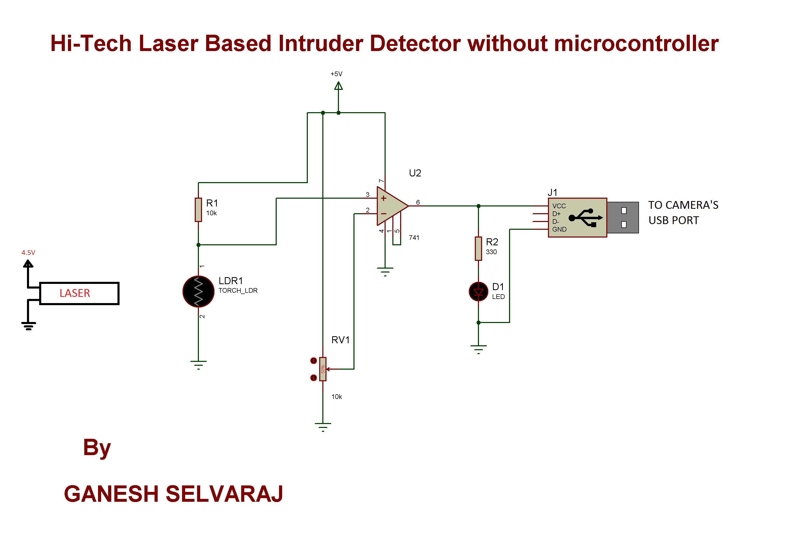
Circuit Diagrams

Circuit-Diagram-Laser-Light-and-LM741-OPAMP-IC-Based-Intruder-Alarm


Filed Under: Electronic Projects
Tagged With: laser
 

Next Article

← Previous Article
Next Article →

Questions related to this article?
👉Ask and discuss on Electro-Tech-Online.com and EDAboard.com forums.


Tell Us What You Think!! Cancel reply

You must be logged in to post a comment.

EE TECH TOOLBOX

“ee
Tech Toolbox: 5G Technology
This Tech Toolbox covers the basics of 5G technology plus a story about how engineers designed and built a prototype DSL router mostly from old cellphone parts. Download this first 5G/wired/wireless communications Tech Toolbox to learn more!

EE Learning Center

EE Learning Center
“engineers
EXPAND YOUR KNOWLEDGE AND STAY CONNECTED
Get the latest info on technologies, tools and strategies for EE professionals.

HAVE A QUESTION?

Have a technical question about an article or other engineering questions? Check out our engineering forums EDABoard.com and Electro-Tech-Online.com where you can get those questions asked and answered by your peers!


RSS EDABOARD.com Discussions

  • Collector Current Low side Has a large drop respect High Side during Miller during Double Pulse Test
  • Diode recovery test Irrm timing.
  • The Analog Gods Hate Me
  • How best to synchronise the UCC38C45?
  • floating node warning in LTSpice

RSS Electro-Tech-Online.com Discussions

  • The Analog Gods Hate Me
  • Display TFT ST7789 (OshonSoft Basic).
  • Fixing board, Easy question HEX SCHMITT
  • Can I make two inputs from one??
  • Home Smoke detectors are all Beeping Batteries are not dead.???

Featured – LoRa/LoRaWan Series

  • What is the LoRaWAN network and how does it work?
  • Understanding LoRa architecture: nodes, gateways, and servers
  • Revolutionizing RF: LoRa applications and advantages
  • How to build a LoRa gateway using Raspberry Pi
  • How LoRa enables long-range communication
  • How communication works between two LoRa end-node devices

Recent Articles

  • How to monitor temperature and humidity on a TFT display with graphics
  • Tria modules integrate edge AI processing with multi-core processors
  • pSemi introduces RF switch with 52 dBm PMAX,PEAK and 90-dBm IIP3 linearity
  • XP Power launches 1.3 kW power supply with 58.9 W/cm³ density
  • How to enable Wi-Fi provisioning in ESP32-based IoT products

EE ENGINEERING TRAINING DAYS

engineering

Submit a Guest Post

submit a guest post
Engineers Garage
  • Analog IC TIps
  • Connector Tips
  • Battery Power Tips
  • DesignFast
  • EDABoard Forums
  • EE World Online
  • Electro-Tech-Online Forums
  • EV Engineering
  • Microcontroller Tips
  • Power Electronic Tips
  • Sensor Tips
  • Test and Measurement Tips
  • 5G Technology World
  • Subscribe to our newsletter
  • About Us
  • Contact Us
  • Advertise

Copyright © 2025 WTWH Media LLC. All Rights Reserved. The material on this site may not be reproduced, distributed, transmitted, cached or otherwise used, except with the prior written permission of WTWH Media
Privacy Policy

Search Engineers Garage

  • Electronic Projects & Tutorials
    • Electronic Projects
      • Arduino Projects
      • AVR
      • Raspberry pi
      • ESP8266
      • BeagleBone
      • 8051 Microcontroller
      • ARM
      • PIC Microcontroller
      • STM32
    • Tutorials
      • Audio Electronics
      • Battery Management
      • Brainwave
      • Electric Vehicles
      • EMI/EMC/RFI
      • Hardware Filters
      • IoT tutorials
      • Power Tutorials
      • Python
      • Sensors
      • USB
      • VHDL
    • Circuit Design
    • Project Videos
    • Components
  • Articles
    • Tech Articles
    • Insight
    • Invention Stories
    • How to
    • What Is
  • News
    • Electronic Product News
    • Business News
    • Company/Start-up News
    • DIY Reviews
    • Guest Post
  • Forums
    • EDABoard.com
    • Electro-Tech-Online
    • EG Forum Archive
  • DigiKey Store
    • Cables, Wires
    • Connectors, Interconnect
    • Discrete
    • Electromechanical
    • Embedded Computers
    • Enclosures, Hardware, Office
    • Integrated Circuits (ICs)
    • Isolators
    • LED/Optoelectronics
    • Passive
    • Power, Circuit Protection
    • Programmers
    • RF, Wireless
    • Semiconductors
    • Sensors, Transducers
    • Test Products
    • Tools
  • Learn
    • eBooks/Tech Tips
    • Design Guides
    • Learning Center
    • Tech Toolboxes
    • Webinars & Digital Events
  • Resources
    • Digital Issues
    • EE Training Days
    • LEAP Awards
    • Podcasts
    • Webinars / Digital Events
    • White Papers
    • Engineering Diversity & Inclusion
    • DesignFast
  • Guest Post Guidelines
  • Advertise
  • Subscribe