Methods/Techniques to drive heavy loads with Microcontrollers
- Transistors
- optocoupler
- Relays
- Mosfets
- SSR(Solid State Relay)
The upper list starts from low power control electronic component(Transistor) to high power control(SSR-Solid State relay). These electronic components can be interfaced with any vendor of microcontrollers Altera, Atmel, Cypress Semiconductor, Maxim Integrated, EPSON Semiconductor, Freescale Semiconductor, Infineon, Intel, Microchip Technology, National Semiconductor, NXP Semiconductors, Panasonic, Parallax, Silicon Laboratories, Silicon Motion, Sony, STMicroelectronics, Texas Instruments, Toshiba. I interfaced the above components in many circuits with different microcontrollers e.g Arduino, Pic, Stm32, 8051, Picaxe, Avr, Atmega, Arm and LPC series etc to control high power loads. The above components can be used with mini computers or development boards such as BeagleBone, Raspberry Pi, Olimex and Xilinx FPGA boards.
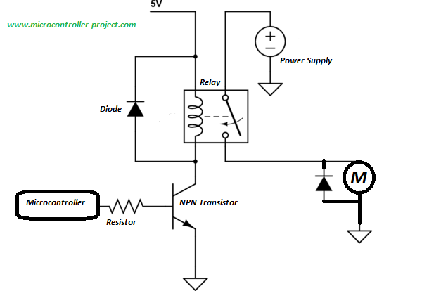
Driving heavy loads with Microcontrollers and Transistors.
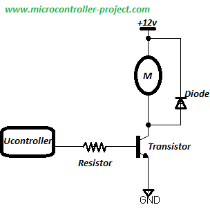
Transistor driving heavy load with microcontroller
|
Generally transistor can handle currents up to 600 mills Amperes and voltage up to 20 volts. The ratings can be little bit high or low. The maximum power that a transistor can handle is 12 watts to 18 watts. This power is enough to control loads that falls below 18 watt power such as dc toy motors and dc bulbs etc. But still this power is not enough to control the loads that consumes continuous current of 1 amperes.
|
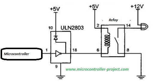
Transistor can be arranged together for high current gain. Most popular configuration is darlington configuration in which a high current gain is achieved by small voltage switch. Many commercial ic’s are available in market that contain the transistors build in side them. Such as ULN2003 and ULN2803 contains darlington transistor array in side them.
|
Darlington circuit configuration and ULN2003 ic pin out is shown on the right hand side. ULN2003 contains 7 darlington configuration in side it. Its easy to use the ic instead of making the darlington configuration by our own. Ic consumes less space and less connections are required.
|
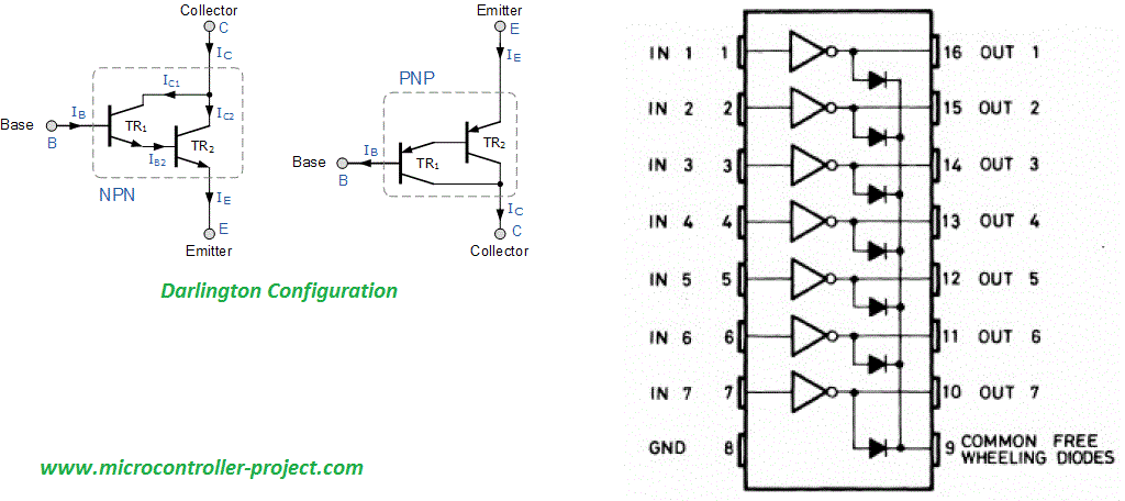
Darlington configuration in ULN2803
|
Driving heavy loads with Microcontrollers and Optocoupler.
Optocoupler driving heavy loads with microcontroller
|
A general optocoupler circuit with connections to microcontroller is shown on the left hand side. A motor is driven by the microcontroller. Optocuplers are used in many circuits to isolate the circuit from the other. This way danger of high spikes is eliminated. If their is a high spike it will only blow off the optocoupler at the remain circuit will remain safe. It is generally used in high valuable circuit cores. To isolate them with high current regulation circuits.
Optocouplers can handle more power than transistors. Such as FOD3180 optocoupler that can handle continuous 2 Amperes of current and 10 volts to 20 volts. DC Optocouplers can control power up to 40 watts to 60 watts. Unlike transistors which are not useful in switching AC loads. Optocouplers can be used to control heavy AC loads. This will be discussed in SSR(Solid State relays) topic. |
Driving heavy loads with Microcontrollers and Relays.
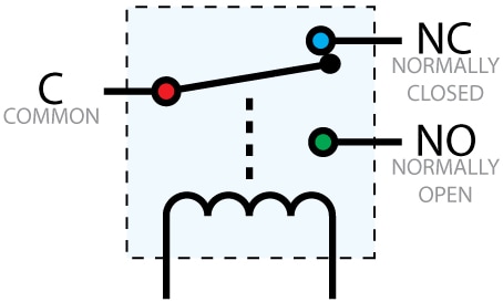 Relay Pinout
of current flow between common and normally close line. But when a sufficient voltage is applied across the coil of relay the common pin shorts with the NO(Normally Open) pin. Making a path of current flow between common and normally open pin. The path is a straight mechanical connection between wires. A 5 pin relay is shown on left hand side. Relay’s comes in many packages such as single pole single through, double pole and double through(DBDT), Single pole double trough(SPST) etc.
Relays can directly be controlled with microcontroller pins. Small +3 volt and +5 volt relays can directly be controlled trough microcontrollers GPIO(General purpose input/output) pins. But some relays coils require more current to switch the output channel. In order to supply them sufficient voltage they are derived through transistors. Relays can handle 10-15 Amperes of current and 110-220 volts. We can easily control a 500 watt load with standard relays.
Relay driving heavy loads with microcontroller and transistor
|
Relay driving heavy loads with microcontroller and uln2003
|
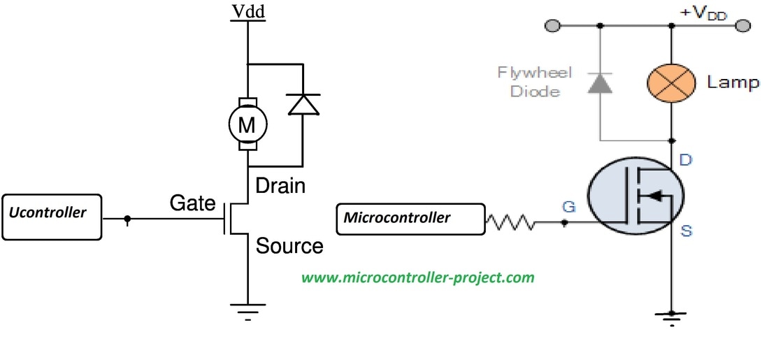
Driving heavy loads with Microcontrollers and Mosfets.
Driving heavy loads with Microcontrollers and SSR(Solid State Relay)

SSR with microcontroller controling heavy loads
|
In order to fully understand the ssr working we must first understand two electronic components. These components are building block of SSR. The components them self are evolved from transistors working concept.
|
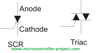 SCR vs TRIAC
The name Triac stands for triode (three electrode) AC switch. It is a thyristor device similar to an SCR, but differs in that it can be triggered into conduction in both directions, in response to a positive or negative gate signal. TRIAC ans SCR symbols are shown on the left hand side. SCR can work like TRIAC if we attach one more SCR in opposite direction to it and gate are combined.SCR and TRAIC are used to control AC loads. They are used to control mains electricity phases etc. They can also work on PWM input. They are widely used in AC circuits to dim lights. Standard dimmers available in market are all comprised of SCR or TRIAC.
A SSR for AC use usually consists of an opto isolator driving a Triac. A SSR for DC use usually consists of an opto isolator driving a power MOSFET.Filed Under: Knowledge Share, Microcontroller Projects

Questions related to this article?
👉Ask and discuss on EDAboard.com and Electro-Tech-Online.com forums.
Tell Us What You Think!!
You must be logged in to post a comment.