The process of rotating the valve handle can be automated by attaching a motor to valve handle that rotates itself and so the valve too on a remote signal. Since, the valve needs to be rotated at fixed angles to restrict the water flow by specific amounts; a servo motor is suitable for the purpose. While DC motors rotate continuously and maintain rotation due to momentum and inertia, a servo motor is designed to rotate at specific angles and stop at the angle rotated. The angle of rotation can be anywhere between 0° to 180°. A servomotor can be driven by a microcontroller or microcontroller board by sending PWM (Pulse Width Modulated) signal.
In this project 434 MHz RF module is used to send remote control signal and a servo motor is rotated at fixed angles of 0°, 45°, 80°, and 160°. The RF Module is capable of transmitting 4-bit data from one end to another; therefore, to rotate servo motor at four different angles, the four control signals can be directly interpreted in the form of 4 bit’s statuses. The control signals are triggered by pressing switches to alter the statuses of the data bits and the control signal is interpreted by an Arduino board to drive the servo motor. The motor is not installed on a valve handle during the project but can be done when tried.
Components Required
| Sr. No. | Components Required | Quantity |
|---|---|---|
| 1 | RF Tx Module(434 MHz) | 1 |
| 2 | RF Rx Module(434 MHz) | 1 |
| 3 | HT12E | 1 |
| 4 | HT12D | 1 |
| 5 | LED | 1 |
| 6 | Resistor – 1KΩ (Quarter watt) | 4 |
| 7 | Resistor – 1MΩ (Quarter watt) | 1 |
| 8 | Resistor – 50KΩ (Quarter watt) | 1 |
| 9 | Arduino pro mini development board | 1 |
| 10 | Mini servo motor ( 8 gm) | 1 |
| 11 | Battery – 9V | 2 |
| 12 | Push button switches | 3 |
| 13 | Breadboard | 4 |
| 14 | Connecting wires |

Fig. 1: Block Diagram of Arduino based Automatic Electronic Valve for Water Supplies
Circuit Connections
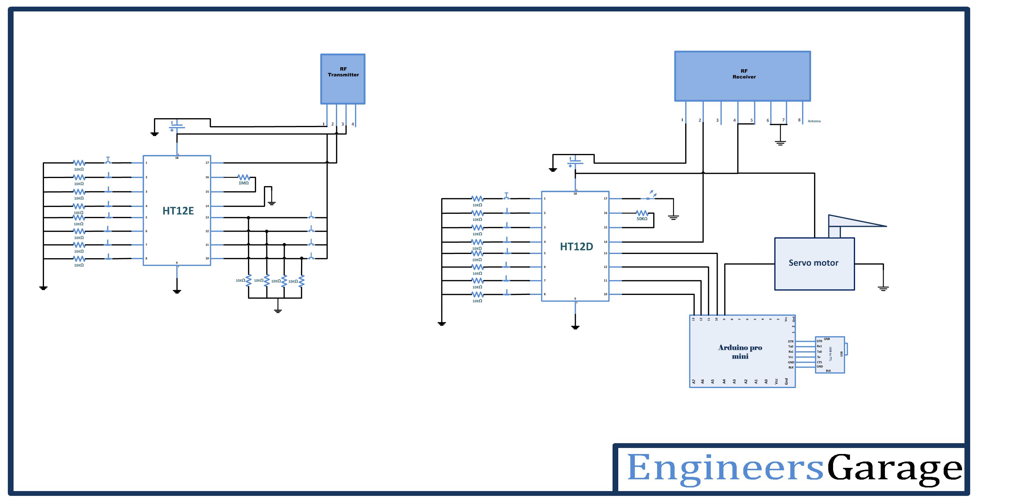
The project comprises of two sections – RF remote and the servomotor control circuit. The RF remote is an RF transmitter section consisting on an RF transmitter connected to HT12E encoder IC by pin 2 and an antenna by pin 4 of the module. The circuit connections of HT12E encoder IC are as specified by the datasheets for basic setup of RF Module. All the address pins of the HT12E are hard-wired to ground to assign it an address byte of 0x00. The pin 14 of the encoder IC is also fixed grounded to enable uninterrupted transmission of control signal. A set of four tactile switches is connected at the data pins of encoder IC for user input. The data pins are by default connected to ground but receives VCC via the tactile switches. The use of antenna is optional but recommended for better range of the RF module. Learn about increasing the operational range of RF module by using antenna and increasing the transmission power.
At the servo motor control circuit, there is an RF receiver section consisting of RF receiver module having its pin 2 connected to HT12D decoder IC and pin 8 to an antenna. The HT12D IC has the basic setup configuration and has all its address bits connected to ground to match the transmitter address 0x00. The data pins of HT12D D0 to D3 are connected to pins 13 down to 10 of Arduino Pro Mini. The Pulse Width Modulated (PWM) output is taken from pin 9 of the Arduino board where the servo control bus is connected. The servo motor is provided ground and VCC from the same supply that powers the Arduino circuit.
How the Circuit Works
This project makes use of RF signal transmission and servo motor control. The RF transmitter by default transmits 0x0 nibble which corresponds to no change in rotation angle of the servo motor. This default angle is 9° or can be any angle to which motor has already been rotated. On pressing any switch, the respective data bit of the encoder gets high. The nibble with new bit status is transmitted and serially feed to the decoder IC. The same 4-bit data is parallel out from the data pins of the decoder IC. So a bit that gets high on encoder side also gets high on the decoder side. The data bits are connected to Arduino pins which are initialized to digital input in the program code and so the change in data bits is read by the Arduino.
When the circuit is powered up, initial code on the Arduino board runs which defaults the servomotor to 9° and wait for remote user input to change the status of servomotor. The code checks for any change in the statuses of the data bits and when a change in a data bit is detected, a PWM signal relevant to the angle assigned for that bit is output from pin 9 of the Arduino board. In this project, D0 to D3 have been assigned to signal following rotation angles of servo motor.
| Data bit | Servo motor Angle |
|---|---|
| D0 | 0° |
| D1 | 45° |
| D2 | 80° |
| D3 | 160° |
The servo motor works on pulse width modulation principle. The greater the pulse width, the greater is the angle to which the servo motor gets rotated. A servo can have a rotation limit of 90°, 180° or an angle greater than 180°. Though servomotors having rotation limit of 90° or 180° are more common in use. This project uses a servo motor having rotation limit of 180°. The motor could have rotated to maximum limit of 180° on receiving a pulse of width say 3 millisecond. Now if a pulse of width 1 millisecond is sent to the servo, it will rotate to an angle of 60°.Similarly if a pulse of width 2 milliseconds is passed to servo, it will get rotated to an angle of 120°. This is basic concept behind controlling servo through PWM.
Since an Arduino board is used in the project, it has already an open-source library to control servos. It is only required to import the standard library and call attach() function of the servo class with rotation angle as the parameter to rotate the servo to the specific angle.
Programming Guide
The program code first imports the standard libraries. The open-source library of Arduino Servo.h is included to implement PWM output. In the initialization code, an object of Servo class is instantiated.
#include <Servo.h>
Servo myservo;
The variables are assigned to read input data bits D0 to D3 as tx1 to tx3 and mapped to pin 13 down to 10 of the Arduino board. The Servo object myservo is assigned pin 9 of the Arduino.
A set up function is called, inside which, the Arduino pins mapped to data pins of decoder IC are made digital input and data rate of the board is set to 9600 bits per second by Serial.begin() function. The servo motor is rotated to an angle of 9 degrees by calling attach() function on the myservo object.
Project Source Code
###
#includeServo myservo; #includeServo myservo; void setup(){ pinMode(tx1,INPUT); pinMode(tx2,INPUT); pinMode(tx3,INPUT); // decoder output microcontroller reading as input. pinMode(tx4,INPUT); Serial.begin(9600); myservo.attach(9); }void loop(){ // reading data and storing in avariable for further use. int Tx1 = digitalRead(tx1); int Tx2 = digitalRead(tx2); int Tx3 = digitalRead(tx3); int Tx4 = digitalRead(tx4); if (Tx1 == HIGH){ myservo.write(0); delay(1500);} else if (Tx2 == HIGH){ myservo.write(45); delay(1500); } else if (Tx3 == HIGH){ myservo.write(80); delay(1500); } else if (Tx4 == HIGH){ myservo.write(160); delay(1500); } }###
Circuit Diagrams
Project Video
Filed Under: Featured Contributions
Filed Under: Featured Contributions

Questions related to this article?
👉Ask and discuss on Electro-Tech-Online.com and EDAboard.com forums.
Tell Us What You Think!!
You must be logged in to post a comment.