INTRODUCTION
BASICS OF HOME AUTOMATION
INTRODUCTION

Fig. 1: Block Diagram of 8051 Microcontroller and DTMF based Home Automation System
NEED OF AUTOMATION
BASICS OF DTMF
INTRODUCTION
What is DTMF code..??
When any key like “1”, “2”, “*”, “#” etc is pressed, a particular code is transmitted. This code consists of two frequencies among which one is higher and second is lower. Following table shows the combination of frequency for respected keys.

Fig. 2: Image showing DTMF Frequencies mapped to a typical numeric keypad
According to above table “8” is combination of lower frequency of 852 Hz and higher frequency of1336 Hz and “#” is of lower frequency of 941 Hz and higher frequency of 1447 Hz. So this is all about DTMF code. Now let’s see how DTMF code is generated, transmitted and decoded in mobile phone system. Here I have only discussed about GSM system.
Transmission of DTMF code in GSM network
Decoding DTMF code

Fig. 3: Table showing digital outputs for DTMF Keys
Keypad

Fig. 4: Graph showing waveform for a DTMF frequency
|
DTMF keypad frequencies (with sound clips) |
||||
|
1209 Hz |
1336 Hz |
1477 Hz |
1633 Hz |
|
|
697 Hz |
||||
|
770 Hz |
||||
|
852 Hz |
||||
|
941 Hz |
# |
|||
Fig. 5: Table showing DTMF Frequencies mapped to key combinations on Keypad
OTHER MULTIPLE FREQUENCY
National telephone systems define other tones that indicate the status of lines, equipment, or the result of calls. Such call progress tones are often also composed of multiple frequencies and are standardized in each country. The Bell System defines them in the Precise tone Plane. However, such signaling systems are not considered to belong to the DTMF system.
BLOCK SCHEMATIC
BLOCK DIAGRAM

Fig. 6: Block Diagram of DTMF Decoder
BLOCK DIAGRAM EXPLANATION
1 MOBILE PHONE
This system is designed for controlling the devices; it includes a mobile phone which is connected to the system via head set. To activate the cellular phone part of the system a call is to be made and as the call is answered, in response the user would enter a three/four(as he/she want) digit password to access the system to control devices. As the caller presses a specific password, the device is turned ON or OFF.
2 . DTMF DECODER IC MT8870
The DTMF is generated in cellular phones. Here, by using a cell phone we control the home appliances from anywhere in the world (In Network Area). When we press any key it generates a frequency after mixing two frequencies and then sends it to the receiver end over communication channel. DTMF decoder IC decodes that particular signal frequency to data and forward to the microcontroller to control the particular device.
3 . ATMEL 80c51 MICRO CONTROLLER
This is the most important block of the system. Microcontroller is the decision making logical device which has its own memory, I/O ports, CPU and Clock circuit embedded on a single chip. It receives inputs from DTMF, makes decision according to it and gives input to the relay driver which drives the corresponding relay and turns the devices on and off.
4 SYSTEM 12V AND 5V POWERSUPPLY
5 RELAY AND DRIVER CIRCUIT
A relay is an electrically operated switch that usually makes use of an electromagnet to mechanically operate a switch. However, other operating principles such as solid-state relays may also be used, Relays are used where it is necessary to control a circuit by a low-power signal (with complete electrical isolation between control and controlled circuits), or where several circuits must be controlled by one signal. The first relays were used in long distance telegraph circuits as amplifiers: they repeated the signal coming in from one circuit and re-transmitted it to another circuit. Relays were used extensively in telephone exchanges and early computers to perform logical operations. Relay driver circuit drives each relay switch by external 12v supply. In the output of the microcontroller as the voltage is less than about 4.5V it won’t be able to switch the relays. In order to avoid such a condition, we will have to provide an intermediate to the driver circuit.
DTMF DECODER IC MT8870
The MT8870D/MT8870D-1 is a complete DTMF receiver integrating both the bandsplit filter and digital decoder functions. The filter section uses switched capacitor techniques for high and low group filters; the decoder uses digital counting techniques to detect and decode all 16 DTMF tone pairs into a 4-bit code. External component count is minimized by on chip provision of a differential input amplifier, clock oscillator and latched three-state bus interface.
FEATURES
APPLICATIONS
PIN DESCRIPTION

Fig. 7: Pin Diagram of MT8870 DTMF Decoder
Fig.(A)

Fig. 8:
Table :(B)
FUNCTIONAL DESCRIPTION
FILTER SELECTION
Separation of the low-group and high group tones is achieved by applying the DTMF signal to the inputs of two sixth-order switched capacitor bandpass filters, the bandwidths of which correspond to the low and high group frequencies. The filter section also incorporates notches at 350 and 440 Hz for exceptional dial tone rejection (see Figure 3). Each filter output is followed by a single order switched capacitor filter section which smoothes the signals prior to limiting. Limiting is performed by high-gain comparators which are provided with hysteresis to prevent detection of unwanted low-level signals. The outputs of the comparators provide full rail logic swings at the frequencies of the incoming DTMF signals.
DECODER SECTION
Following the filter section is a decoder employing digital counting techniques to determine the frequencies of the incoming tones and to verify that they correspond to standard DTMF frequencies. A complex averaging algorithm protects against tone simulation by extraneous signals such as voice while providing tolerance to small frequency deviations and variations. This averaging algorithm has been developed to ensure an optimum combination ofimmunity to talk-off and tolerate the presence of interfering frequencies (third tones) and noise. When the detector recognizes the presence of two valid tones (this is referred to as the “signal condition” in some industry specifications) the “Early Steering” (ESt) output will go to an active state. Any subsequent loss of signal condition will cause ESt to assume an inactive state (see “Steering Circuit”).
ATMEL AT89c51 MICROCONTRLLER
FEATURES
BLOCK DIAGRAM

Fig. 9: Internal Block Diagram of 8051 Microcontroller
PIN CONFIGURATION

Fig. 10: Pin Diagram of AT89C51 8051 Microcontroller
Fig (A) Pin configuration

Fig. 11: Table showing pin configuration of AT89C51 8051 Microcontroller
ELECTRICAL CHARACTERISTICS
HARDWARE IMPLEMENTATION
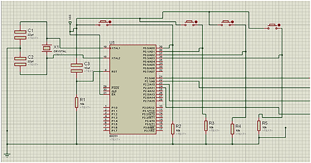
CIRCUIT DIAGRAMS
Fig. 12: Circuit Diagram of DTMF Decoder
(Check the circuit diagram tab for complete circuit for Home Automation using DTMF and 8051)

Fig. 13: Circuit Diagram of relay driver used for controlling home appliances

Fig. 14: Circuit Diagram of Relay Driver used for controlling home appliances
CIRCUIT DESIGN
POWER SUPPLY

Fig. 15: Circuit Diagram of Rectifier and 7812 12V Power Regulator
1 TRANSFORMER : A transformer is an electrical device that transfers energy between two or more circuits through electromagnetic induction. A varying current in the transformer’s primary winding creates a varying magnetic flux in the core and a varying magnetic field impinging on the secondary winding. This varying magnetic field at the secondary induces a varying electromotive force (EMF) or voltage in the secondary winding. Making use of Faraday’s Law in conjunction with high magnetic permeability core properties, transformers can thus be designed to efficiently change AC voltages from one voltage level to another within power networks.

Fig. 16: Typical Image of 12V Step-Down Transformer
2 REGULATED POWER SUPPLY: Here our main power supply source is 12V AC to DC rectifier circuit. We have used full wave bridge rectifier, regulated IC 7812 and IC 7805A regulated power supply. IC 7805A is an embedded circuit that converts unregulated AC in to a constant Dc volt with the help of a rectifier.. Its function is to supply a stable voltage to a circuit or device that must be operated within certain power supply limits. The output from the regulated power supply may be alternating or unidirectional, but it’s always nearly DC. Below mentioned fig shows the power supply unit.

Fig. 17: Pin Diagram of 7812 Voltage Regulator IC
Here we used 12v and 5v regulated supply because microcontroller usually works at +5V. So to get that voltage, we need a voltage regulator as 5v for which we have used an IC 7805. The current capacity of this regulator is 1A. If you need more current either use a number of them in parallel or switch to another voltage regulator whose current capacity is more.

Fig. 18: Pin Diagram of 7805 Voltage Regulator IC
RELAY AND DRIVER
A relay is an electrically operated switch. Many relays use an electromagnet to mechanically operate a switch, but other operating principles are also used, such as solid-state relays. Relays are used where it is necessary to control a circuit by a low-power signal (with complete electrical isolation between control and controlled circuits), or where several circuits must be controlled by one signal. The first relays were used in long distance telegraph circuits as amplifiers: they repeated the signal coming in from one circuit and re-transmitted it to another circuit. Relays were used extensively in telephone exchanges and early computers to perform logical operations.

Fig. 19: Typical Image of Relays
One of the serious problems in relay operated circuits is the relay clicking or chattering during the on/off of the relay driver transistor. This problem is severe if the input circuit is a light/temperature sensor. By using a simple tip, this problem can be avoided. Below is the circuit of a relay driver using the NPN transistor BC 548. The relay is connected between the positive rail and the collector of the transistor. When the input signal passes through the I K resistor to the base of the transistor, it conducts and pulls the relay. By adding a 470 uF electrolytic capacitor at the base of the relay driver transistor, a short lag can be induced so that the transistor switches on only if the input signal is persisting. Again, even if the input signal ceases, the transistor remains conducting till the capacitor discharges completely. This avoids relay clicking and offers clean switching of the relay. Relay Driver Circuit transistor relay driver circuit schematic*(meaning not clear) Another 470uF capacitor is added parallel to the relay coil which maintains steady current so that relay clicking can be avoided if the power supply varies.
VARIOUS DEVICES USED
RESISTORS
A resistor is a two-terminal electrical or electronic component that opposes an electric current by producing a voltage drop between its terminals in accordance with Ohm’s law. It states that the electrical resistance is equal to the voltage dropped across the resistor divided by the current through the resistor while the temperature remains the same. Resistors are used as a part of electrical networks and electronic circuits.

Fig. 20: Image of Resistors used in Rectifier Circuit
CAPACITORS
A capacitor is an electrical or electronic device that can store energy in the electric field between a pair of conductors. The process of storing energy in the capacitor is known as “charging” and involves electric charges of equal magnitude but opposite polarity, building up on each plate. Capacitors are often used in electric and electronic circuits as energy-storage devices. They can also be used to differentiate between high frequency and low frequency signals. This property makes them useful in electronic filters.

Fig. 21: Image of Capacitors used in Rectifier Circuit
CRYSTAL OSCILLATOR

Fig. 22: Typical Image of Crystal Oscillator
CONECTING MOBILE PHONE WITH MT8870
|
|

Fig. 23: Pin Description of 3.5 MM Audio Jack used with DTMF Decoder
SOFTWARE IMPLIMENTATION
COMPILER & IDE

Fig. 24: Block Represeentation of C Program Compilation
We are writing the program in embedded C .The compiler that we used is KIEL and the IDE is AVR Studio
PROGRAM ALGORITHM
FLOW CHART

Fig. 25: Flow Diagram of C Code used for detection of DTMF Frequencies
PCB DESIGN AND FABRICATION
Printed circuit board fabrication is one of the essential and the prominent step in the formation of one electronic device .In this section we are explaining about the formation of PCB. The design of a PCB can be considered as the last step in electronic circuit designing .In the electronic circuit performances and reliability depends on the productivity of the PCB. Assembling and service ability also on the design .A proper ensure that various components are interconnected as there the circuit diagram. Once they have been placed on the PCB in their proper position and subsequently soldered. PCB design and fabrication techniques have undergone so much of development that it has become a subject in itself. Double sided PCBs with plated through holes (PTH) flexible PCBs etc. are only some of the developments .The single sided PCBs are usually using the print and etch method and double –sided plates through hole boards are made by print ,plate and etch method. The production of multilayer boards used both the techniques.
PREPARING LAY-OUT
TRANSFERRING THE LAY OUT TO COPPER
The layout made on the white paper should be redrawn on the copper clad using paint or nail polish.

Fig. 26: PCB Layout of DTMF based Home Automation Circuit
CONCLUSION
This project was completed within constraints of time, availability of resources and the scopes of the subject covered in the curriculum till the present semester. Here we have made an attempt to reduce human effort by Automation. Our automation could perform various tasks like industrial applications. We hope our project will be beneficial to various fields.
Circuit Diagrams
Filed Under: Electronic Projects

Questions related to this article?
👉Ask and discuss on EDAboard.com and Electro-Tech-Online.com forums.
Tell Us What You Think!!
You must be logged in to post a comment.