This is a home automation project in which the home appliances will be controlled from the personal computer using a Matlab-based desktop application. Matlab stands for MATrix LABoratory and it is a multi-paradigm numerical computing environment. It is a fourth-generation programming language. A programming language developed by the MathWorks. It allows matrix manipulation, plotting of data and algorithms and the best part is that it also creates the user interfaces like buttons, graphs, etc. MATLAB processes each and every data in the MATRIX form. So matrix manipulation is very important part of MATLAB. The Matlab will be utilized to develop a desktop application with GUI to control switching appliances ON or OFF.
The desktop application interacts with Arduino UNO which is interfaced to RF module. The Arduino board acts as transmitter circuit for sending control signals to switch devices ON or OFF over RF frequency. The devices to be managed are interfaced to an RF receiver section which controls the devices based on the signals received from transmitter circuit.
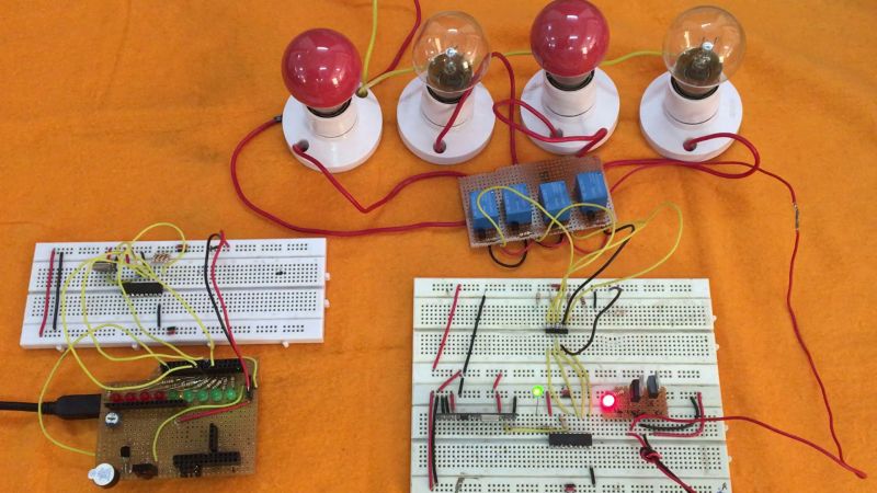
Fig. 1: Prototype of Matlab and ArduinoIO based Home Automation System
The advantage of using Matlab is that it has an extension – ArduinoIO available which allows programming Arduino directly from the Matlab. A developer only needs to develop the desktop application and mainly the GUI of the application and the code for Arduino to interact with Matlab is automatically generated by the Matlab. A file generated on adding ArduinoIO allows Arduino to interact with the Matlab application and allows the Arduino board to be directly controlled by the Matlab.
In the project, four AC appliances will be controlled that will be interfaced to decoder IC of the RF receiver via 12V relays.
COMPONENTS REQUIRED
Receiver Side:
1. Arduino UNO
2. Tx RF 433MHz module
3. Encoder IC (HT12E)
4. 1K and 1M ohm resistor
5. 5mm LED
6. 10K ohm PRESET
Transmitter Side:
1. 7805 and 7812 voltage regulators
2. Rx RF 433MHz module
3. Decoder IC (HT12D)
4. 1K and 47K ohm resistor
5. 5mm LED
6. 12v Relay
7. 10K ohm PRESET
8. Transistor (BC547)
9. Bulb holder
10. TWO pin plug
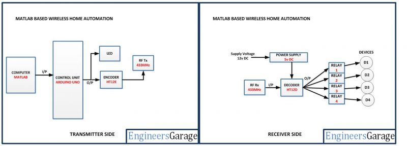
Fig. 2: Block Diagram of Matlab and ArduinoIO based Home Automation System
CIRCUIT CONNECTIONS
The project will utilize two circuits – receiver circuit where the appliances to be controlled will be interfaced and transmitter circuit that will connect to the PC through Arduino board.
The transmitter circuit will be built around Arduino UNO and have the following sections assembled together.
Personal Computer – The personal computer will run the Matlab based desktop application to control the appliances. The PC will be connected to the Arduino board via COM port. While programming the desktop application, it will be important to note down the COM port number.
Arduino UNO – The Arduino board will be receiving the control signals from the desktop application over serial communication. The Matlab will automatically generate an Arduino sketch which will read the control data over serial port and transmit relevant RF data to control the appliances.
16X2 LCD – The LCD will be used to show the status of the devices controlled by the home automation system. It is connected to the Arduino board by connecting its data pins to pins 2 to 5 of the Arduino board. The RS and E pins of the LCD are connected to pins 13 and 12 of the Arduino UNO respectively. The RW pin of the LCD is grounded.

Fig. 3: Table listing circuit connections between Arduino Uno and Character LCD
The standard open-source library for interfacing LCD with Arduino UNO is used in the project. The library works as expected and needs no changes or modifications.
RF Transmitter – The RF transmitter will be used to transmit the control data to the receiver circuit. The RF transmitter module is a small PCB sub assembly. The pin configuration of transmitter module is as follows.

Fig. 4: Table listing pin configuration of RF Transmitter
The serialized data from encoder is received at pin 2 of the module and passed on to the antenna from pin 4 of the module.
HT12E IC – The HT12E IC converts the parallel data into serial data for passing it to the RF transmitter. HT12E encoder IC belongs to the 212 series of encoders. It is paired with 212 series of decoders having the same number of addresses and data format. HT12E is capable of encoding 12 bits, out of them 8 are address bits and 4 are data bits. Thus the encoded signal is a serialized 12-bit parallel data comprising of 4-bit data to be transferred appended with the address byte.
The receiver circuit will be more or less the basic RF receiver circuit connecting RF receiver and the HT12D decoder IC. The appliances will be connected to the data pins of the decoder IC via relay circuits. The relay circuits will have 12V relays connected to the data pins via BC547 transistor connected in common emitter configuration.
RF Receiver – The RF receiver detects the radio signal carrying the control data. The RF receiver module has 8 pins and has following pin configuration.
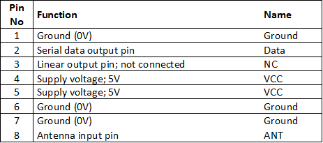
Fig. 5: Table listing pin configuration of RF Receiver
HT12D Decoder – The signal detected from the RF receiver is passed to the HT12D decoder. It converts the serial data back to the parallel data after separating data and addresses. HT12D belongs to the 212 series of decoders and can be paired with 212 series of encoders having the same number of addresses and data format. HT12D is capable of decoding 12 bits, out of them 8 are address bits and 4 are data bits. The appliances will be controlled by the parallel data received on the HT12D decoder IC. The data bits of the decoder IC will be used to drive the relays. The address byte of the decoder IC should be same as of the encoder IC to match the transmitter and receiver circuits. In the project, address byte of both the receiver and transmitter modules is set to 0x00.
Relays – The 12V 2A relays are used to switch the AC appliances ON or OFF in the project. The relays are connected to the data pins of the HT12D IC via BS547 transistor circuits connected in a common emitter configuration. The phase wire from the AC supply is provided at the COM terminal of the relays. When a HIGH logic is received at the data pins of HT12D, the COM point switches from NC to NO point where a relay short-circuits the phase with the neutral wire switching the supply to the appliance ON.
Power Supply – Both the circuits will be powered by 5V DC supply. The 7805 voltage regulator is used to supply the desired voltage. The power can be drawn from a regular battery which can be connected to the 7805 IC. The IC has three pins – pin 1 should be connected to anode of the battery, pin 2 and 3 with the cathode (common ground). The 5V DC should be drawn from the pin 3 of the IC.
HOW THE PROJECT WORKS
The home automation system developed in this project is operated by the Matlab Application. The user needs to plug the Arduino based transmitter circuit to the serial port of the PC and launch the Matlab based desktop application. It is important to note down the COM port number beforehand. The Matlab automatically generates the Arduino code by its ArduinoIO extension which should be burnt to the Arduino board. The generated Arduino sketch automatically reads the control data from the desktop application and drive digital Input and Output pins of the Arduino to display status of devices on LCD and send control data to switch appliances ON or OFF. The Arduino sketch actually allows Arduino to operate according to the Matlab application and allows the board to interact with the Matlab platform.
Programming Guide
For designing the desktop application on Matlab, first ArduinoIO Add-on for Matlab needs to be downloaded and added to the Matlab Add-On folder. The ArduinoIO for MATLAB is an ADD-ON which contains all the functionality of Arduino UNO. Download the Arduino UNO from the MathWorks website. A Zip file will be available for download. After downloading, Unzip the Add-On and copy/paste the folder inside the Matlab installation folder.
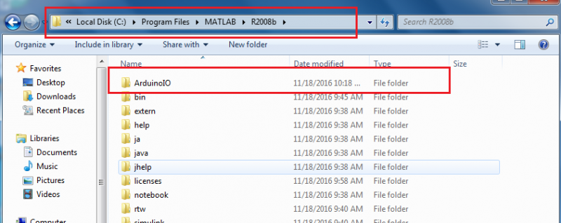
Fig. 6: Screenshot of ArduinoIO folder on Windows
ArduinoIO folder contains examples, pde, simulinks and some important file.
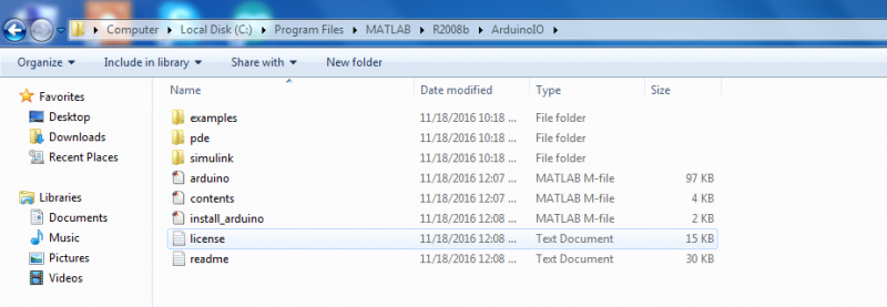
Fig. 7: Screenshot of different sub-folders of ArduinoIO folder on Windows
Installing ArduinoIO and burning add-on file to Arduino
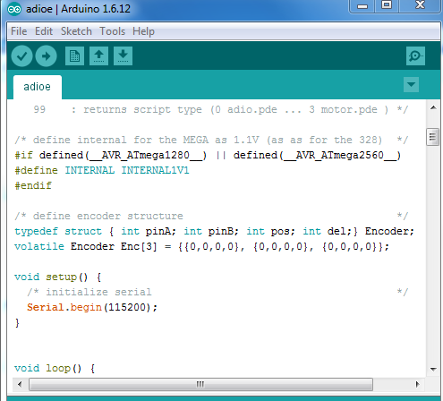
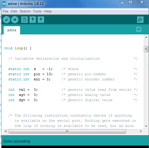
During the project development, MATLAB2008b was used. Open MATLAB and set the Current directory of MATLAB to the ArduinoIO folder. Enter a file name in the command window and press ENTER. The ArduinoIO Add-On will be installed on the Matlab after this. A file named adioe.pde will be generated on adding the ArduinoIO to Matlab. The file needs to be burnt to Arduino UNO to enable the board to interact with the Matlab application.

Fig. 8: Screenshot of ArduinoIO command window on Windows
Creating GUI of the Matlab Based Desktop Application
The application will be used to switch the devices ON or OFF. Its GUI will have the buttons to switch the individual device ON or OFF or switch all the devices ON or OFF.
Got to File>New >GUI or click on the button highlighted with red colour.

Fig. 9: Screenshot of navigation for new GUI on Matlab
Click on Blank GUI(Default), a new window will open where GUI can be designed. Designing the GUI this application will only use Buttons and Frame.
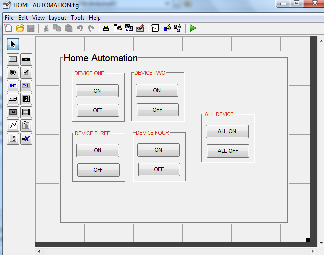
Fig. 10: Screenshot of GUI designed on Matlab
After completing design, it needs to be saved. As soon as it is saved, a code for creation of the GUI will be automatically generated by the MATLAB.
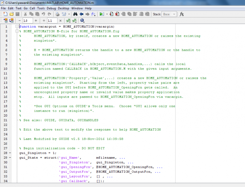
Fig. 11: Screenshot of GUI code on Matlab
After designing GUI, a Matlab code needs to be written to operate the Arduino board and the adioe.pde file needs to be burnt to the Arduino board before testing the home automation application. Once the code is burnt to the Arduino board, the board is ready to interact with the Matlab application.
Writing Matlab Application
The code follows the following syntax – set(<object Tag name>,property,value); Like: set(handles.threeON,’BackgroundColor’,’g’); This line of code is written to change the background colour to green when it is clicked.
The GUI developed will look like this during operation.
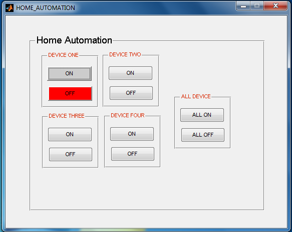
Fig. 12: Screenshot of GUI for Home Automation System

Fig. 13: Screenshot of GUI for Home Automation System

Fig. 14: Screenshot of GUI for Home Automation System
When a button gets pressed a HIGH or LOW is set in Matlab just like in Arduino. Like for the first button to ON the device.
a.digitalWrite(6,1); statement refers to writing HIGH logic to the pin 6 of Arduino UNO from MATLAB. And a set statement is used to change the colour of the button at run time. The value of colour can be written in r, g or b or in the [r g b] format.
The following code is used to turn OFF a device
To switch all the devices ON the following code is used
Arduino Code
Project Source Code
###
#include <SoftwareSerial.h>// import the serial library #include <LiquidCrystal.h>//import the LCD library LiquidCrystal lcd(13, 12, 6, 5, 4, 3);// Pins used for RS,E,D4,D5,D6,D7 int Data; // the data received from the app store here int a=0,b=0,c=0,d=0,e=0; //used for key press or not int ONE=7; //Digital pin 6 isS used to ON relay 1 int TWO=8; //Digital pin 7 is used to ON relay 2 int THREE=9; //Digital pin 8 is used to ON relay 3 int FOUR=10; //Digital pin 9 is used to ON relay 4 void setup() { // Setup code to initialize all the user and predefined functions Serial.begin(9600); //Software serial initialization lcd.begin(16,2);//LCD 16x2 initialization pinMode(ONE, OUTPUT);// Set pim 6 as OUTPUT pinMode(TWO, OUTPUT);// Set pim 7 as OUTPUT pinMode(THREE, OUTPUT); // Set pim 8 as OUTPUT pinMode(FOUR, OUTPUT); // Set pim 9 as OUTPUT lcd.setCursor(0,0); //Initially set the cursor position of LCD to 1st Columb 1st row. lcd.print("Engineers Garage");//After initialising print data lcd.setCursor(0,1); //Initially set the cursor position of LCD to 1st Columb 2nd row. lcd.print(" "); //print blank to clear all the data on LCD delay(3000); lcd.setCursor(0,0); lcd.print(" PC Based Home "); lcd.setCursor(0,1); lcd.print(" Automation "); delay(3000); lcd.setCursor(0,0); lcd.print("D1:OFF D2:OFF"); //Initially dispaly all are OFF lcd.setCursor(0,1); lcd.print("D3:OFF D4:OFF");//Initially dispaly all are OFF } void loop() { if (Serial.available()) // wait for the data to be available at the receiver buffer. { Data=Serial.read(); // Read the dat store it in the variable. Serial.write(Data); if(Data=='W' && a==0){ // Checking the received number if found with the given condition a=1; // "a" variable used to checked if button is pressed or not. digitalWrite(ONE,1); //if pressed send HIGH value to the pin number 6 lcd.setCursor(3,0); lcd.print("ON "); //Display ON in the location 1st ROW and 3rd COLUMB } else if (Data=='W' && a==1) {// if character 'W' pressed .... a=0; digitalWrite(ONE,0); lcd.setCursor(3,0); lcd.print("OFF"); } else if (Data=='S' && b==0) {// if character 'S' pressed .... b=1; digitalWrite(TWO,1); lcd.setCursor(13,0); lcd.print("ON "); } else if (Data=='S' && b==1) {// if character 'S' pressed .... b=0; digitalWrite(TWO,0); lcd.setCursor(13,0); lcd.print("OFF "); } else if(Data=='A' && c==0) { // if character 'A' pressed .... c=1; digitalWrite(THREE,1); lcd.setCursor(3,1); lcd.print("ON "); } else if (Data=='A' && c==1) {// if character 'A' pressed .... c=0; digitalWrite(THREE,0); lcd.setCursor(3,1); lcd.print("OFF "); } else if (Data=='D' && d==0) {// if character 'D' pressed .... d=1; digitalWrite(FOUR,1); lcd.setCursor(13,1); lcd.print("ON "); } else if (Data=='D' && d==1) {// if character 'D' pressed .... d=0; digitalWrite(FOUR,0); lcd.setCursor(13,1); lcd.print("OFF "); } else if (Data=='Q' && e==0) {// if character 'Q' pressed .... e=1; digitalWrite(ONE,1); digitalWrite(TWO,1); digitalWrite(THREE,1); digitalWrite(FOUR,1); lcd.setCursor(0,0); lcd.print("D1:ON D2:ON "); //Initially dispaly all are OFF lcd.setCursor(0,1); lcd.print("D3:ON D4:ON ");//Initially dispaly all are OFF } else if (Data=='Q' && e==1) {// if character 'Q' pressed .... e=0; digitalWrite(ONE,0); digitalWrite(TWO,0); digitalWrite(THREE,0); digitalWrite(FOUR,0); lcd.setCursor(0,0); lcd.print("D1:OFF D2:OFF"); //Initially dispaly all are OFF lcd.setCursor(0,1); lcd.print("D3:OFF D4:OFF");//Initially dispaly all are OFF } else; } delay(100); }###
Project Video
Filed Under: Electronic Projects
Filed Under: Electronic Projects


Questions related to this article?
👉Ask and discuss on Electro-Tech-Online.com and EDAboard.com forums.
Tell Us What You Think!!
You must be logged in to post a comment.