Home automation is the latest craze. Remote controlling every electrical and electronic appliance on a handheld remote is a comfort for sure. Obviously, a home automation application is not feasible without a wireless interface between the handheld remote and appliances.
This project is a demonstration of a simple home automation application where the user can switch remote appliances ON or OFF with a handheld remote controller. The application is made on 434 MHz RF module where the module is connecting the remote and the relay circuit for switching the appliances. A 434 MHz RF module has an operational range of 50-60 metre which can be extended to 300-350 metres using antennas with the module and increasing the transmission power. Therefore the project can be easily installed and is suitable for a house or building of any size.
In the project a single RF receiver has been paired to RF transmitter controlling four appliances. Multiple receivers can be connected with a transmitter by matching their address byte to that of the transmitter where transmitter can be configured to have different address byte at different times. This way any number of appliances (Maximum 128 * 4) can be remote controlled.
Components Required
| Sr. No. | Components Required | Quantity Required |
|---|---|---|
| 1 | RF Rx Module(434Mhz) | 1 |
| 2 | RF Tx Module(434Mhz) | 1 |
| 3 | HT12E | 1 |
| 4 | HT12D | 1 |
| 5 | LED | 1 |
| 6 | Resistor – 100Ω (Quarter watt) | 4 |
| 7 | Resistor – 1MΩ (Quarter watt) | 1 |
| 8 | Resistor – 50KΩ (Quarter watt) | 1 |
| 9 | Battery – 9V | 2 |
| 10 | Single change over type relay | 4 |
| 11 | 1N4007 Diode | 4 |
| 12 | Light bulb | 4 |
| 13 | Transistor BC547 | 4 |
| 14 | Resistor – 1KΩ (Quarter watt) | 4 |
| 15 | Push button switches | 4 |
| 16 | Breadboard | |
| 17 | Connecting wires |
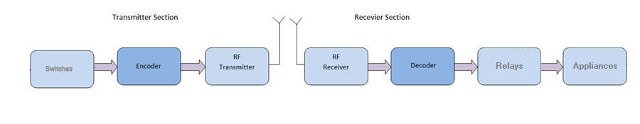
BLOCK DIAGRAM
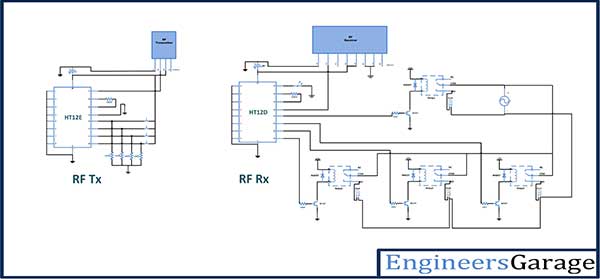
Circuit Connections
There are two circuits in the project – Remote controller circuit and the relay circuit. The remote controller circuit is just the RF transmitter section. The circuit connections of RF module are done as in set up of the basic model of RF Transmitter and Receiver. In addition to the setup of RF module, four switches has been connected at the data pins 10 to 13 designated as D0 to D3 of the encoder IC HT12E. These Push-to-on switches are connected through 10K ohm pull-up resistors to ground. The address pins 1 to 8 of the encoder IC are hard wired to ground to assign the RF transmitter an address of 0x00. The pin 14 of the encoder IC which is active low is also hard-wired to ground to enable uninterrupted transmission of control signal to the RF receiver.

At the relay circuit, an RF receiver is used and the loads are connected at the data pins 10 to 13 designated as D0 to D3 of the decoder IC HT12D through the relays. The address pins 1 to 8 of the decoder IC HT12D are hard wired to ground in order to match the 0x00 address of the RF transmitter. Since, the transmitter has been configured for uninterrupted transmission, any change in the status of switches at the transmitter end immediately reflect a change in on/off status of the relays and thus the appliances at the receiver end.
How the circuit Works
The RF module transmits the 4-bit data which is used as control signal in the project. By default, the data pins of the encoder HT12E receive a HIGH signal as they are connected to VCC by default via 10K ohm resistors. Therefore, by default HIGH bits are transmitted and same HIGH bits are received at the data pins of decoder IC HT12D and the relays remain off as current flows from base to emitter of the transistors. The push-to-on switches are connected to the data pins with other terminal of each switch connected to the ground. When a switch is pressed, the respective pin starts receiving a LOW signal. Since the pin 14 of encoder IC is hard-wired to ground and transmitter generates an uninterrupted transmission of data, as a LOW signal is detected at a data pin of the encoder IC, a LOW signal corresponding to that data bit is immediately transmitted and a LOW bit is decoded at the respective data pin of the decoder IC HT12D. When a LOW signal is received at a data pin of the decoder IC, current starts flowing through collector to emitter of the respective transistor and the respective relay gets operated. Thus the appliance is switched ON after receiving a LOW bit at the respective data pin of the decoder IC.

If the respective switch at encoder IC is pressed off, the corresponding data bit at the encoder is again set to HIGH and a HIGH bit is received at the respective data bit of the decoder IC. Thereof, the appliance connected to the respective data pin of the decoder IC through relay is again switched to OFF.
Project Source Code
Project Source Code
###
//Program to###
Circuit Diagrams
Filed Under: Featured Contributions

Questions related to this article?
👉Ask and discuss on Electro-Tech-Online.com and EDAboard.com forums.
Tell Us What You Think!!
You must be logged in to post a comment.