You can program 8051 microcontrollers in assembly and c. I recommend to first know about the assembly instructions then move on to the c instructions. Assembly instructions gives in depth knowledge of each register and its individual bits functionality. While in c programming most of the configurations are hidden and they are cascaded with the code during compiling and linking process. However in c language we can use inline assembly code with c. This technique is utilized to properly configure and debug the code in case of unknown errors.
Project Requirements
- 89c51 or 89c52 microcontroller
- One LED(Light Emitting Diode)
- Crystal(11.0592 MHz)
- Resistor 1k t0 4.7k ohm
- Two 33-pf Capacitors
- Power Supply
89c51 microcontroller Blink led circuit diagram
|
The circuit of the project is pretty straight forward. We are going to blink an led connected to pin#1 of 89c51 microcontroller. Pin#1 corresponds to microcontroller Port-1 pin#0. The pin is initialized as output pin in the code. External clock source ceramic crystal is connected to Pins 18 & 19 of 89c51 microcontroller. Crystal is connected to microcontroller in parallel to two 33-pf capacitors. 11.0592Mhz crystal is used in the project. Apply Vcc(+5v) to Pins 31 & 40 of 89c51. Ground pin#20. Now we are done all the necessary connections are made. Circuit Diagram of blinking led with 89c51 microcontroller is given at the right side.
Led polarity is anode facing the power supply and cathode is connected to port#1 pin#0. |

Blinking Led with 8051(89c51,89c52)
|
Note: I am using keil software to write my code to blink an led. If you are using any other software to write code for 8051 microcontroller. Then first check which library that software made compulsory to be included for writing code of 8051 series microcontrollers. Keil made it compulsory to include the reg51.h header file in the codes that are written for 8051 series microcontrollers. Actually the compiler that is working with keil needs this header file to compile the code and generate Hex code for you.
Then the statement sbit Led=P1^0; is initializing port#1 pin#0. Now we can use Port-1 Pin#0 with the name of Led. Next delay(value) function here is actually generating some arbitrary delay for us. If Led switches on, we want it to remain in this state for some time so we give some delay before executing the off instruction. You can see the two for loops in the delay function. These two for loops are providing us random delay. The first loop runs number of times for the value which is given to it, and second loop runs 5 times for each iteration of the first loop. We usually pass some big number as parameter to the function and this huge number makes the for loop runs for some seconds to minutes depending on our given integer value. You can also use the internal timers of the 8051 for delays but since this tutorial is for the beginners so you should adopt the easy way.
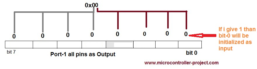
In the main() function the instruction P1=0x00; is initializing our Port-1 as output. It is necessary to initialize each port as input our output before using it in the program. Since my Led is connected to Port-1 Pin#0 that’s why I am initializing Port-1 as output.
0x00; is a hexadecimal command caring 8-bit instruction. If we translate it in binary it becomes P1=00000000. Since Port-1 of microcontroller consists of 8-Pins. This 8-bit instruction is written to each single pin of microcontroller. If 0 is written on Pin it initializes the pin as output. If 1 is written it initializes the pin as input. can easily be written to the microcontroller port and each bit represent a particular port pin of micro controller.
- First I made Led=1 which switches on my led.
- Then Some Delay() Keeps Led in on state.
- After Delay() I made Led=0 which switches off the led.
- Then Some Delay() keeps led in switch off state.
After the above cycle is completed while loop starts again and this makes the led to seem like blinking.
Filed Under: Knowledge Share, Microcontroller Projects

Questions related to this article?
👉Ask and discuss on Electro-Tech-Online.com and EDAboard.com forums.
Tell Us What You Think!!
You must be logged in to post a comment.