You’ve likely seen or heard of at least one of the following:
- A smart luggage trolley at an airport, or a rail or bus station, that’s motor or battery-powered and automatically follows its “owner.”
- A smart cart at a department store, follows the customer who’s using it.
- A smart luggage bag that’s paired with its owner’s smartphone and automatically follows that person.
These are examples of an “object-following robot.” This project is based on this concept. The robot will be programmed to search for a nearby object and, once found, will follow it.
Our robot here uses an ultrasonic distance measurement (UDM) sensor to find an object and measure its distance to it. It employs a servo motor to rotate the UDM sensor and is powered by two DC motors. The controlling circuit of our robot is built using an Arduino Nano board.
Check it out here:
What’s required
Here’s what you’ll need to get started:
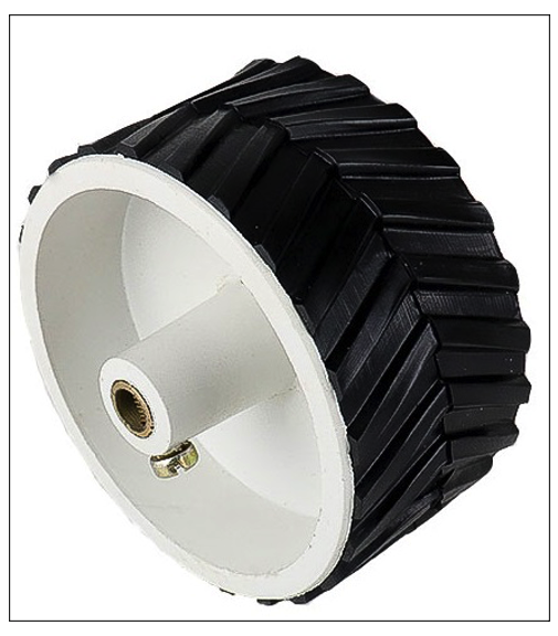
1. Wheels
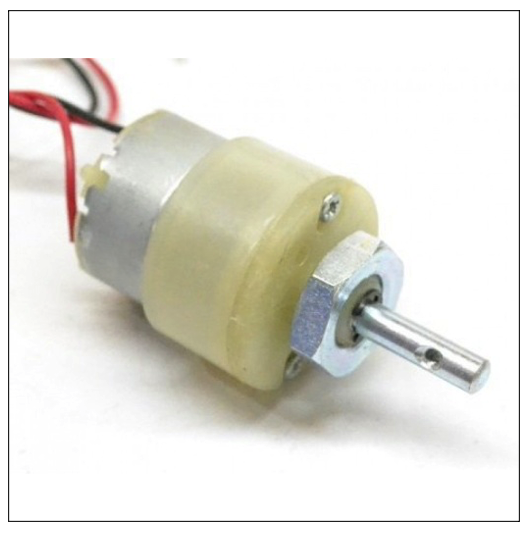
2. DC gear motors (200-300 RPM)
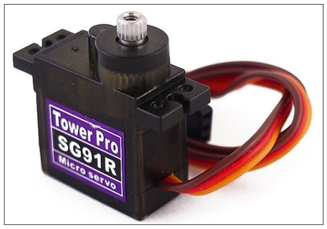
3. Mini DC servo motor
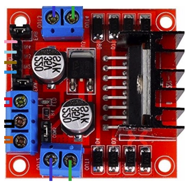
4. L298 dual DC motor driver module
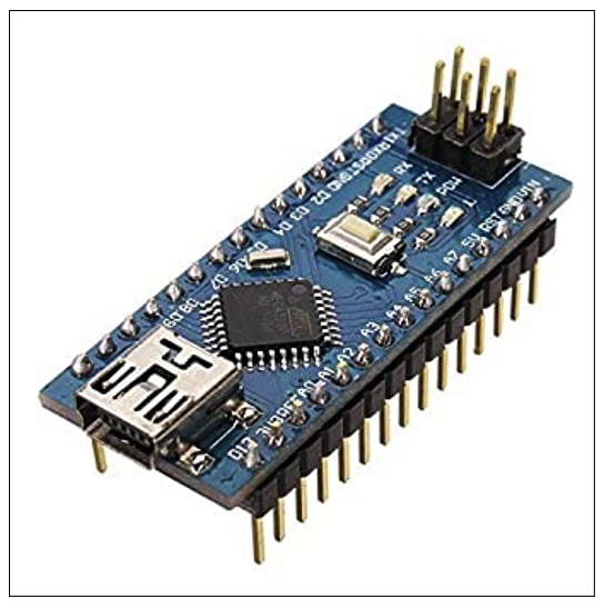
5. Arduino Nano board
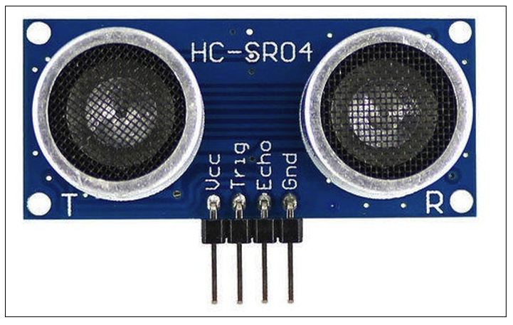
6. UDM sensor HC SR04
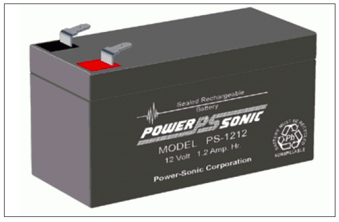
7. A12 V battery
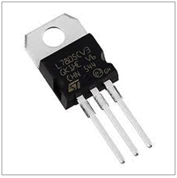
8. Voltage regulator 7805
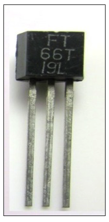
9. A UM66 melody tone generator
10. A small 8 ohm speaker

Robot construction
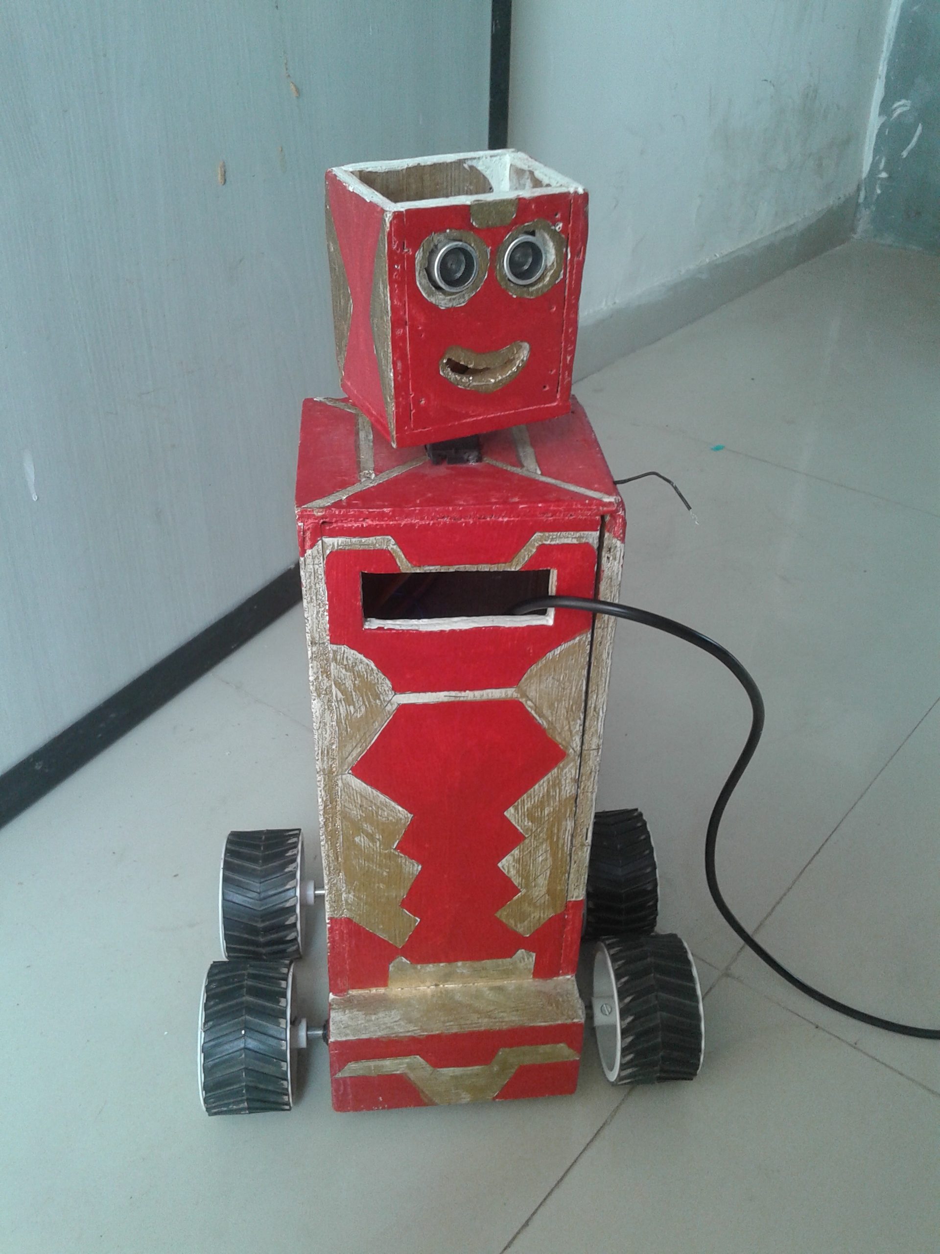
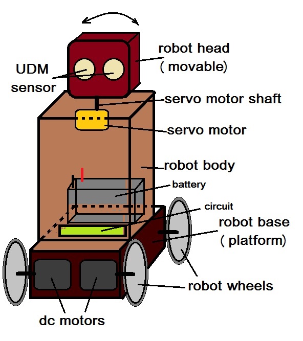
The full robot is built using thin, wooden ply or sheets. Divide the robot into three sections:
1. Base (platform) – houses two DC motors where the wheels are attached. Two additional free wheels are also attached to this base, which all help move the robot in the required direction.
2. Main body – houses the main circuit of the robot and the battery. The servo motor is fixed to the top of this body.
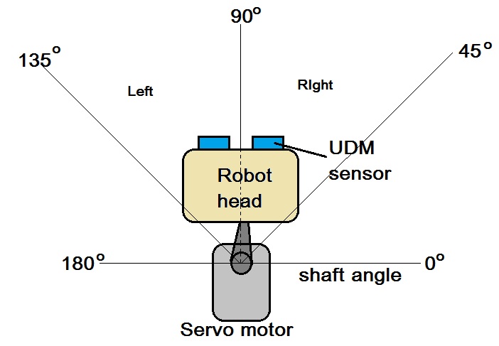
3. Robot head – attached to servo motor shaft and houses the UDM sensor. It can move in different directions.
This figure offers a visual representation of each of the robot’s parts:
After the robot body is completed, let’s build its controlling circuit next.
System block diagram:
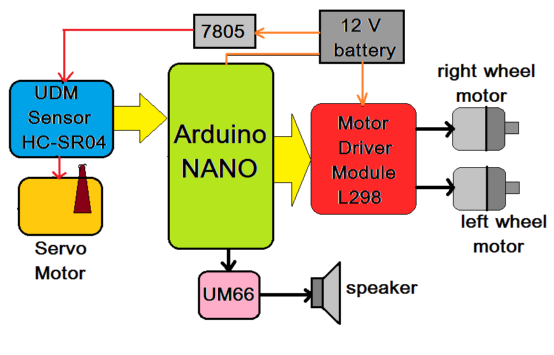
As shown in this diagram, the major building blocks of the robot include the:
- UDM sensor HC SR04: used to find a nearby object and measure its distance from the robot
- Dual DC motor driver module L298: used to drive both DC motors, providing the required voltage and current to each one
- LM7805 voltage regulator: used to provide 5V supply to the UDM sensor and power the servo motor via the battery
- UM66 tone generator speaker: generates melodious audio tone through a speaker, which is used to provide the audio output
- Two DC motors: used to drive the robot’s rear wheels, moving the robot forward and backward, as well as left and right
- One servo motor: used to rotate the robot’s head (using the UDM sensor) back and forth (CW and CCW) — from 45 to 135 degrees
- 12 V battery: supplies both DC motors and the motor driver module, as well as the Arduino board
- Arduino Nano development board: the main building block, or brain of the system and software program.
The Arduino board is responsible for the functionality of the robot, performing tasks such as:
- Searching for and detecting an object
- Measuring its distance using the UDM sensor
- Rotating the servo motor clockwise (CW) and counter-clockwise (CCW) to scan the area using the UDM
- Driving the two DC motors to move the robot forward or to take left or right turns
- Continuously tracking the object and its distance by using the UDM and following it via the DC motors
- Playing an audio tone through the speaker using the UM66
Now, let’s review the system in detail, starting with the circuit diagram and then its operation.
Circuit diagram:

As shown in this diagram, the circuit is built using a UDM sensor HC SR04, dual DC motor driver module L298, an LM7805 voltage regulator, and an Arduino Nano development board.
The UDM sensor HC SR04 has four pins: VCC, GND, Trigger, and Echo.
- The VCC pin connects to LM7805’s 5 V of output
- The GND pin connects with the circuit’s common ground
- The Trigger pin is an input pin that connects with Arduino’s D7 pin
- The Echo pin is an output pin that connects with Arduino’s D6 pin
The servo motor has a three-wire interface: VCC, GND, and Signal.
- LM7805 provides a 5V-supply to the VCC.
- The pulse width modulation (PWM) signal is given to the signal pin from Arduino’s D10 pin
Arduino’s pins D2 to D5 drive the two DC motors through the L298 driver. These pins connect to the motor driver module’s input and the DC motors connect with the motor driver’s output.
The motor driver requires two supplies: 12 V from the battery for the motors and 5 V from the LM7805 for internal biasing and operation .
The UM66 has three pins: input, output, and ground.
- The input pin connects with Arduino’s D12 pin
- The output pin connects with the speaker
The LM7805 gets 12 V input from the battery and generates 5 V of the regulated output. The output is given to the servo motor, UDM sensor, and L298 motor driver module.
The operation
The main task of this robot is to search for a nearby object and then follow it, keeping a maximum distance of one foot (30 cm) behind it. If the object stops, the robot will get as close as 10 cm to it before also stopping.
If this object moves fast enough that’s it’s more than one foot away from the robot, the robot will stop and search for a new object that’s closer to it.
- The robot’s operation begins by searching for a nearby object.
- The Arduino board will give the PWM signal to the servo motor to rotate it CCW from 45o to 135o in step of 5o (the robot’s head will move slowly from right to left).
- As the robot’s head moves, the microcontroller continuously searches for a nearby object by using the UDM sensor. It offers a trigger signal to the sensor and waits for an echo signal in return.
- If no object is located after one complete cycle, the microcontroller will rotate the servo motor CCW from 135o to 45o (and the robot’s head will move from right to left) and will search again.
- If an object is located in front of the UDM sensor, it will send an echo signal back to the microcontroller, which then calculates its distance from the object.
- If the distance is more than 30 cm, it will ignore it and continue to search for a closer object.
- If the distance is less than 30 cm, the microcontroller will stop the servo motor and angle it in the direction of the nearby object.
- If the servo motor’s angle is less than 90o (meaning between 45o to 90o), then the robot will direct both DC motors to turn right.
- And if the motor angle is more than 90o, the robot will direct the DC motors to turn left.
- After taking a left or right turn, the microcontroller will drive both motors forward so the robot approaches the object.
- While the robot is moving forward, the microcontroller continuously measures this object’s distance by using the UDM sensor. The robot will continue to move forward until it reaches a distance of less than 30 cm from the object.
At this point, there can be three possible outcomes:
1. If the object is not moving – the microcontroller will stop the motors (and, therefore, the robot) once the robot is 10 cm away from the object. Then, the microcontroller will trigger the sensor to begin searching for a new object.
2. If the object is moving – the robot moves forward and follows the object.
3. If the object moves more than 30 cm away from the robot – the microcontroller stops the motors and, therefore, the robot and triggers the sensor to begin searching for a new object.
These operations are available in a program that’s downloaded into the internal FLASH memory of Arduino board ATMega328. This program is written in C/C++ language in the Arduino IDE software tool. It’s compiled using the same software and then downloaded into Arduino Nano board via a USB.
Software program
You may also like:


Filed Under: Arduino., Electronic Projects, Microcontroller Projects

Questions related to this article?
👉Ask and discuss on EDAboard.com and Electro-Tech-Online.com forums.
Tell Us What You Think!!
You must be logged in to post a comment.