Scratch is a programming tool for creating embedded games,stories and animations without using any written codings, rather using visually organized syntax which is in blocks with a drag-and-drop interface. One can use these blocks according to one’s requirement, scratch’s control of hardware is not only limited to the external inputs such as the keyboard and mouse.This article explains how to configure Scratch to extend its power to access GPIO(General Purpose Input and Output) of the Raspberry Pi.
In this tutorial a Raspberrypi board is booted with Ubuntu OS and is connected to the Ethernet port of a Windows7 PC. The board is connected to the internet as explained in the article Connecting the Raspberry pi to the internet. The IP address of the Raspberrypi board has been obtained to remote login in the TUI using the PUTTY and is remotely accessed using VNC.
Open terminal and type the following command:
wget http://bit.ly/1wxrqdp -O isgh7.sh
The file will be downloaded and saved in the SD card.

Fig. 2: Dowloading Scratch Command For Raspberry Pi
Or download the file directly to another computer and copy it to your Raspberry Pi Shared folder.
Execute the File to install Scratch GPIO by use of the following command:
bash isgh7.sh
If not logged as the root user, add the sudo before the command like:
sudo bash isgh7.sh
and press Enter
This will install all the necessary extra software and some examples.

Fig. 3: Installing Scratch And Other Softwares
This installation will create two desktop icons – ScratchGPIO7 is used for beginners for simple circuits and ScratchGPIO 7Plus is used by experts with a lot of add-on boards.
How it works:
Scratch can also shout called “broadcast” to anything which is called as listening and also hear called “receive” any other things which are shouting too.
The python program called “scratch_gpio_handler.py” will runs in the background and it is set up to listen any of these broadcast messages and turn them into GPIO actions.
The current scratch_gpio_handler.py has the GPIO pins fixed to the following inputs and outputs. The pin numbers given, are the pins as counted on the P1 GPIO header itself.
Broadcast Commands:
Outputs (21,18,16,15,13,12,11)
|
Command |
Alt Command |
Result |
|
pinXon |
pinXhigh |
Turns pin X ON |
|
pinXoff |
pinXlow |
Turns pin X OFF |
|
allon |
allhigh |
Turns all pins ON |
|
alloff |
allow |
Turns all pins OFF |
|
pinpattern1010111 |
|
Sets each pin ON or OFF depending on 1 or 0 [21,18,16,15,13,12,11] |
Making led blink:

Fig. 4: Making Led Blink Using Scratch
The green flag in the play window is to start the code, here we have used forever loop block to make the led blink forever.
Sensing inputs:
Inputs (26,24,22,19,10,7)

Fig. 5: Sensing Inputs In Scratch To Access GPIO
In scratch separate sensing block is available where sensor value consists of a slider which includes the input pins can be used accordingly. We can use this variable block to compare with binary values using control blocks.
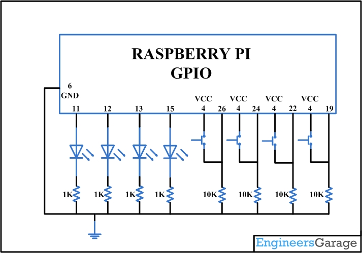
Controlling of LED using buttons:
Controlling of four led using four switches is visually coded here and working is demonstrated in the video.

Fig. 7: Controlling LED Using Buttons
You may also like:


Circuit Diagrams
Project Video
Filed Under: More Editor's Picks, Raspberry pi, Tutorials
Filed Under: More Editor's Picks, Raspberry pi, Tutorials

Questions related to this article?
👉Ask and discuss on EDAboard.com and Electro-Tech-Online.com forums.
Tell Us What You Think!!
You must be logged in to post a comment.