In the previous tutorial, we learned how to connect a Zig-Bee module with a PC using FTDI USB to Serial converter cable or USB cable and an Arduino board and various AT commands were tested. In this tutorial, a Zig-Bee module will be used to read analog data and transmit it to another module. The Zig-Bee module comes with 6 Analog Input pins and 8 digital input output pins. Any analog input pin can be used to read analog voltage. For reading analog voltage, a reference voltage needs to be set for the module. The process of reading analog data from Zig-Bee module and passing the data to another module is called Analog I/O Line Passing.
Components Required –
1) X-Bee Modules – 2
2) Arduino UNO
3) Breadboards
4) Connecting Wires
5) FTDI USB to Serial converter cable
6) PC
7) 10K Pot
Circuit Connections –
In this project, two X bee series 1 (S1) modules are used. One module serves as Transmitter and the another one as Receiver. Both the modules will be connected PCs for passing AT commands and monitoring Data transfer. A X-Bee module is a 20-pin module with the following pin configuration –

For connecting a Zig-Bee module with PC, FTDI USB to Serial converter cable can be used. The convertor cable has four pins – VCC, Ground, RX and TX. These pins should be connected to the X-Bee module in the following manner –

Another way of connecting the X-Bee module with PC is connecting it via Arduino board. The PC and Arduino board can be connected by an USB cable. The RX and TX pin of the Arduino can be connected to the Tx and RX pins of the Zig-Bee module and Reset pin of the Arduino UNO can be grounded. Now by loading the ‘Bare Minimum’ Arduino Sketch on the board, it can be used for serial communication with the X-Bee module.
Both the modules need to be powered by 3.3 V batteries. according to the pin configuration of the X-Bee modules, the positive terminal of the battery should be connected at pin 1 of the module and negative terminal to the pin 10 of the module.
The X-Bee module to be used as transmitter will be fed analog input via a 10K potentiometer. One terminal of a 10K ohm potentiometer should be connected to VCC and the other terminal to the ground. The middle terminal of the pot should be connected at pin 20 of the Zig-Bee module as Analog Input 0 of the module will be used to read analog data. The pin will be configured to analog input using AT commands. The pin 14 of the module should be connected to 3.3 V as the pin 14 is the reference voltage pin which will be set to 3.3 V.
The X-Bee module to be used as receiver will have an LED connected at pin 6 of the module. The pin 6 of the X-Bee is Pulse Width Modulation Output 0. The pin will be used to generate a PWM signal which will vary according to the potentiometer. The LED will fade according to the potentiometer due to PWM signal varying according to the analog input at the transmitter module.
How the circuit works –
The AT commands will be used to configure both the module. The transmitter module will be configured to read analog data and pair with receiver module to pass the data to it. The commands will be transferred using ‘CoolTerm’ application by the PC. At the transmitter module following configuration parameters will be required to be changed –
1) PAN ID
2) Destination Low Address
3) Source Address
4) Data I/O pin 0 (20th pin)
5) I/O sampling rate
These parameters will be set to the following values using the AT commands –
1) PAN ID = 0x3332
2) Destination Low Address = 0x22
3) Source Address = 0x24
4) Data I/O pin (D0) = 0x02 (Passing 0x02 configures the pin to Analog input)
5) I/O Sampling rate = 0x1E (30 seconds)
The following AT commands are passed for changing the configuration parameters for the transmitter module –
The receiver module will be configured to pair with the transmitter module and generate PWM at pin 6 according to the passed analog data. At the receiver module following configuration parameters will be required to be changed –
1) PAN ID
2) Destination Low Address
3) Source Address
4) PWM pin (6th pin)
5) Set ATIA
These parameters will be set to the following values using the AT commands –
1) PAN ID = 0x3332 (Setting the PAN ID same as transmitter Address pairs the two modules)
2) Destination Low Address = 0x24 (Receiver’s DL Address should be same as Transmitter Source address)
3) Source Address = 0x22 (Transmitter Destination Low address should be same as the Receiver’s Source address)
4) PWM pin (Po) (pin 6 of the module) = 0x02 ( Passing 0x02 configures the pin to Analog output)
5) Set “ATIA” as Source address of the transmitter (24) so that pin 6 (PWM) of the receiver follows the changes at pin 20 of the transmitter.
ATIA is Address command. It helps in enabling the pin output mode updates from the other X-Bee Radio. It should be noted that D0 at transmitter is Digital pin and Received data also in the form of digital but PWM output is Analog, because PWM acts as a DAC here.
The following AT commands are passed for changing the configuration parameters for the receiver module –
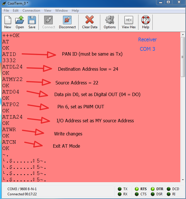
After configuring each module, the settings must be saved by sending ATWR Command and finally exit from the AT mode by using ‘ATCN’ command. After configuring the modules and saving the configurations, on changing the potentiometer value on transmitter side, the LED on receiver side will fade in and out.

This tutorial demonstrated analog I/O Line Passing between two X-Bee modules. In the next tutorial on Zig-Bee interface, reading digital data on X-Bee module and passing it to another X-Bee module will be done.
You may also like:


Project Source Code
Project Source Code
###
//Program to###
Filed Under: Tutorials

Questions related to this article?
👉Ask and discuss on Electro-Tech-Online.com and EDAboard.com forums.
Tell Us What You Think!!
You must be logged in to post a comment.