Much like the name suggests, DC motor controllers control the speed and direction of a DC motor. To change the direction of the motor, however, the supply it receives must be reversed. And, to vary the DC motor speed, a pulse-width modulation (PWM) signal or wave must be applied to it.
As the pulse width increases, the average voltage applied to the motor will also increase — and vice versa. This means that the DC motor speed varies with the pulse width.
PMW has become a commonly used method to do just this. But another option that’s gaining popularity is controlling the speed and direction of a DC motor by using a joystick. How it works: when the joystick is at the center position, the DC motor stops. When the joystick is moved up or down, the motor rotates in the same direction — either forward or in reverse.
Additionally, the further away from the center the joystick is pushed (in either direction), the faster the motor speed will be in that same direction. So, users can control the DC motor speed in this way.
The joystick control method for DC motors is currently used in several different applications, including as:
1. Remote-controlled (RC) toys, such as planes, helicopters, boats, cars, etc.
2. Video camera cranes
3. Industrial Jogg controllers
4. Robotic arms or for robotic vehicles
5. Surveillance camera controllers
There are many other applications as well, where the DC motor that drives the load is controlled by a joystick. In some, only the direction of the motor is altered (such as for RC toys) whereas in other applications, both the direction and speed are varied (such as for video camera cranes, jog controls, etc.).
The project given below demonstrates using a joystick to control the speed and direction of a DC motor. It uses a two-axis resistive joystick using an Arduino NANO development board to control an L298 motor driver.
Circuit diagram
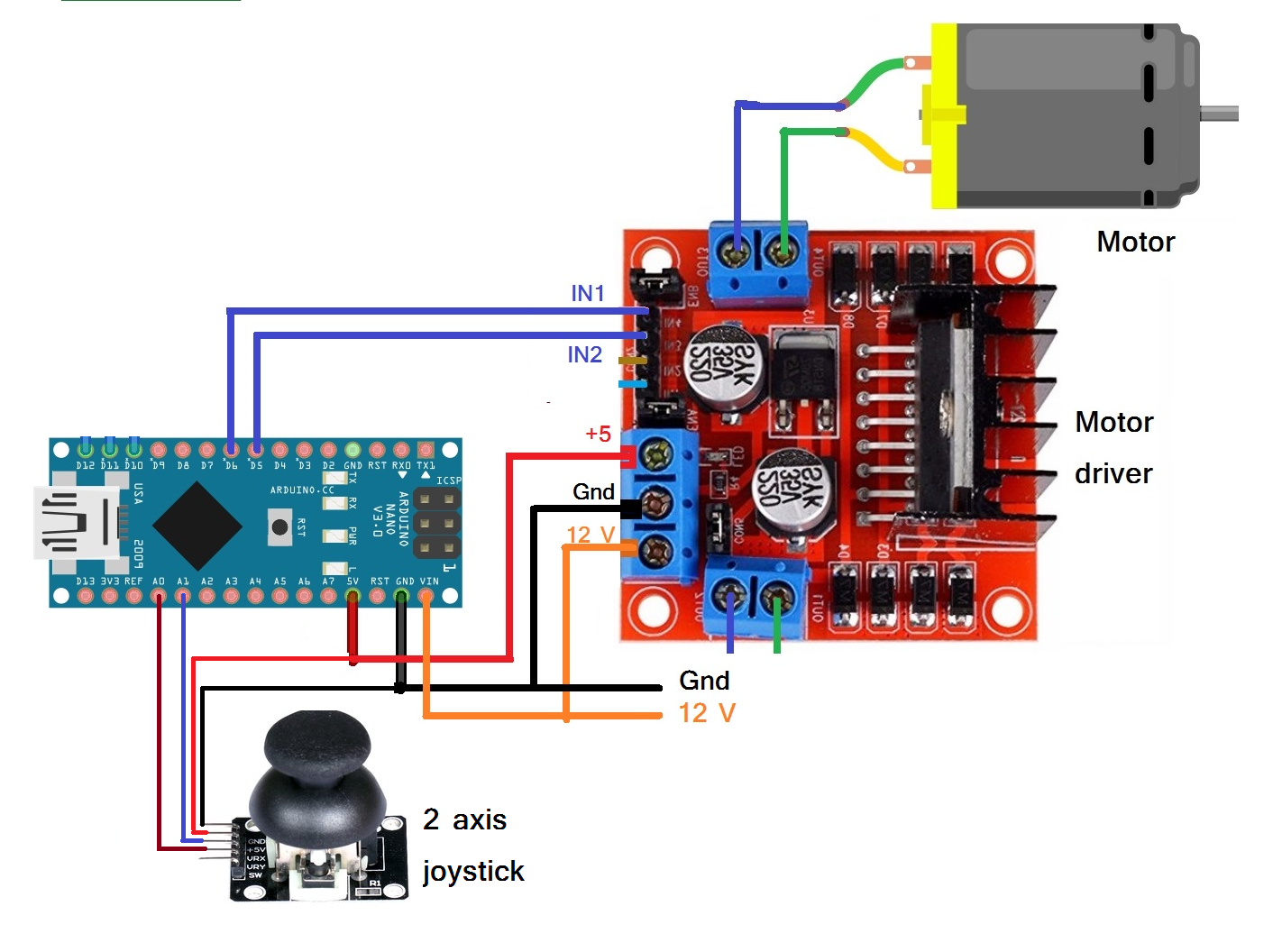
The circuit is built using three major building blocks with an Arduino NANO board, a two-axis resistive joystick, and an L298 motor driver:
- The joystick has five interfacing pins: Vcc, GND, X, Y, and button. The Vcc pin is given a 5V supply from the Arduino board and the GND pin is connected with the board’s ground.
- The X and Y pins are analog output that’s connected with Arduino’s analog pins A0 and A1. The button pin is not used here.
- The PWM output from Arduino’s pins D5 and D6 are connected to the motor driver input pins IN1 and IN2. They drive the motor through the motor driver.
- The 12 V DC motor is connected at the output of the motor driver’s OUT1 and OUT2
- Both Arduino and the motor driver are given 12V of external supply.
Circuit working and operation:
Circuit working and operation:
- Initially, when the joystick is in the center or rest position, the motor is stopped. As the joystick is gradually moved up, the motor starts running at a slow speed in a clockwise direction (forward). As the joystick is moved further up from the center, the motor speed increases. When the joystick is up as far as it can go, the motor attains its full speed forward.
- As the joystick moves back to the center (rest) position, the motor speed starts decreasing and will stop.
- Similarly, when the joystick is moved downward, the motor starts running in an anti-clockwise direction (reverse). As the joystick is moved further from the center, the motor speed increases until it. When the joystick is down as far as it can go, the motor attains its full speed in reverse.
- When the joystick is moved fully left or right, the motor runs in either forward or reverse at full speed.
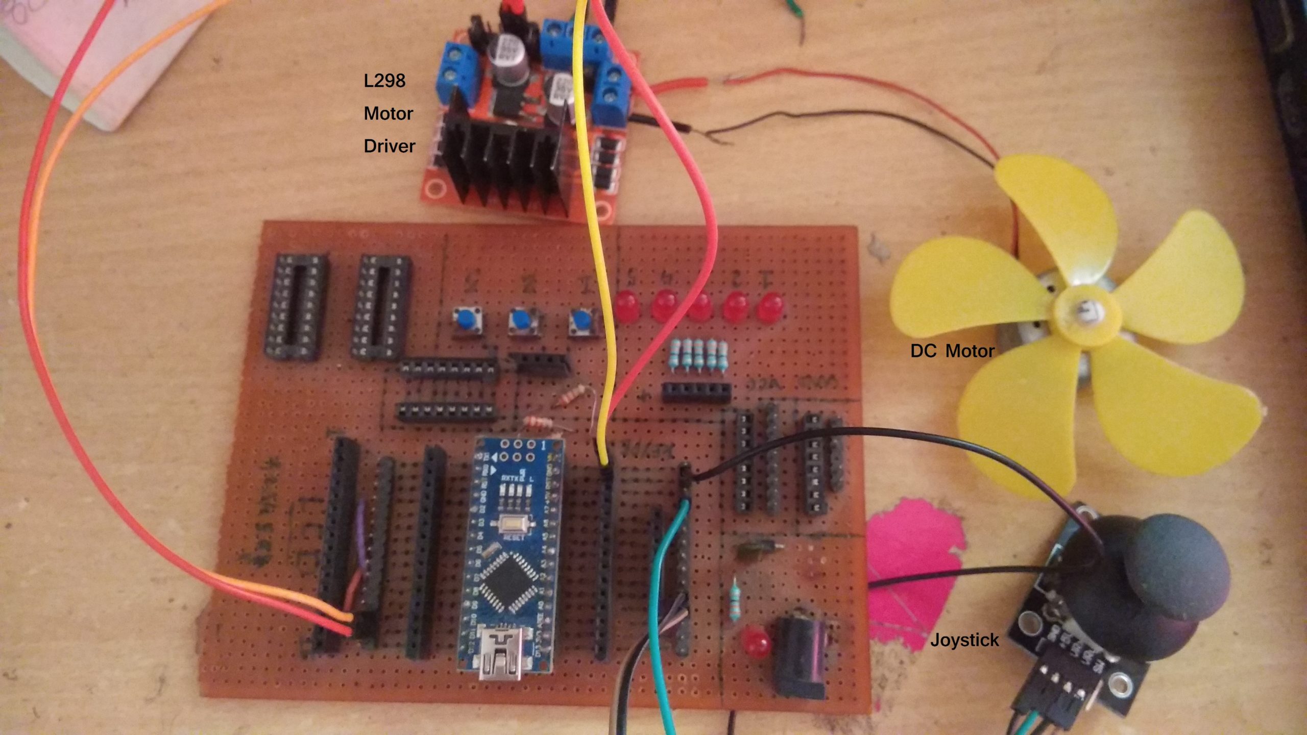
Next, let’s review the circuit in action:
- Moving the joystick toward the center or rest position always slows down the motor. It will completely stop when in the center position.
- When the joystick is moved up or down, its internal resistance (the potentiometer) increases or decreases. Essentially, this increases or decreases the analog output voltage for pin X.
- Arduino will read the analog voltage and convert it into a digital value, which ranges from 0 to 1023, based on whether the joystick moves fully up or down.
- When the joystick is in the center position, Arduino receives a value of about 510. When it’s moved upward, the value gradually increases from 510 to 1023 max. Similarly, when the joystick is moved downward, the value decreases from 510 to 0 max.
- Based on these values, Arduino generates PWM on pins D5 and D6. When the joystick moves upward, the PWM value gradually increases from 0 to 255 (0 – 100%) on pin D5 (and the motor speed accelerates forward). When the joystick moves downward, the PWM value increases on pin D6 (and the motor speed accelerates in a reverse direction).
- Similarly, moving the joystick to the left or right will increase or decrease the analog output on pin Y. Arduino will read the analog voltage and convert it into a digital value.
- When the joystick is moved to the right, the value will be more than 750. As a result, Arduino will give 100% of the PWM signal to pin D5 (and the motor will run forward at full speed). When the joystick is moved to the left, the value will be less than 250. Now, Arduino will give 100% of the PWM signal to pin D6 (and the motor will run in reverse at full speed).
- The motor speed increases and decreases as the joystick is moved. It will also change directions depending on whether the joystick is moved up or down.
This working of this circuit depends on the program that’s downloaded into the internal memory (FLASH) of Arduino’s microcontroller ATMega328. This program is written using C language, using the Arduino IDE software. It also uses the “DC_Motor” Arduino library that I developed (and it’s available on this website, Engineers Garage).
Software program:
#include <DC_Motor.h>
DC_Motor dcm(5,6,1);
int motor_speed,set_speed;
void setup()
{
}
void loop()
{
int x_value,y_value;
x_value = analogRead(A0);
if((x_value>=490) && (x_value<=530)) dcm.motor_speed_zero();
if(x_value>550)
{
set_speed = map(x_value,550,1020,10,100);
dcm.run_motor(1,set_speed);
}
if(x_value<470)
{
set_speed = map(x_value,470,0,10,100);
dcm.run_motor(0,set_speed);
}
y_value = analogRead(A1);
if(y_value>750)
{
dcm.jogg_set_speed(1,100);
}
if(y_value<250)
{
dcm.jogg_set_speed(0,100);
}
}
You may also like:


Filed Under: Arduino, Electronic Projects

Questions related to this article?
👉Ask and discuss on Electro-Tech-Online.com and EDAboard.com forums.
Tell Us What You Think!!
You must be logged in to post a comment.