Engineers Garage

  • Projects and Tutorials
    • Electronic Projects
      • 8051
      • Arduino
      • ARM
      • AVR
      • PIC
      • Raspberry pi
      • STM32
    • Tutorials
    • Circuit Design
    • Project Videos
    • Components
  • Articles
    • Tech Articles
    • Insight
    • Invention Stories
    • How to
    • What Is
  • News
    • Electronic Products News
    • DIY Reviews
    • Guest Post
  • Forums
    • EDABoard.com
    • Electro-Tech-Online
    • EG Forum Archive
  • Digi-Key Store
    • Cables, Wires
    • Connectors, Interconnect
    • Discrete
    • Electromechanical
    • Embedded Computers
    • Enclosures, Hardware, Office
    • Integrated Circuits (ICs)
    • Isolators
    • LED/Optoelectronics
    • Passive
    • Power, Circuit Protection
    • Programmers
    • RF, Wireless
    • Semiconductors
    • Sensors, Transducers
    • Test Products
    • Tools
  • EE Resources
    • DesignFast
    • LEAP Awards
    • Oscilloscope Product Finder
    • White Papers
    • Webinars
  • EE Learning Center
    • Design Guides
      • WiFi & the IOT Design Guide
      • Microcontrollers Design Guide
      • State of the Art Inductors Design Guide
  • Women in Engineering

How To Create Animation On 16×2 LCD Using Arduino- (Part 9/49)

By Ajish Alfred

A microcontroller can communicate with the user by several means including LED display, sound generation, using the serial communication etc. The most commonly found output device in a microcontroller board is an LCD display module. The LCD module makes the system stand-alone since the systems don’t have to rely on an external PC where it can display the data send by using serial communication ports. There are basically two kinds of LCD modules, character LCD modules and graphical LCD modules. A graphical LCD module can display graphics easily, but it doesn’t have built ASCII characters to easily display text. The character LCD modules on the other hand have in-built storage of ASCII characters so that the microcontroller can easily send ASCII values to the module to display the corresponding character.

The LCD module can be made to display letters, numbers, sensor values, clocks etc. They can be also configured as scrolling display also. The LCD module has separate memory where the user can store custom characters like smileys, logos etc. which can then be displayed on the LCD. The LCD display becomes most effective when the microcontroller is coded in such a way that it can display animations on the LCD module.This project demonstrates how it is possible to display small kind of animations in a simple 16*2 LCD module with the help of the Arduino board.


The AVR microcontroller boards which are provided with all the basic circuitry for the operation of the microcontroller which has been flashed with the Arduino boot-loader are called Arduino boards. The Arduino board has all the required circuitary to get the built-in AVR microcontroller running. When it comes to programming the Arduino board anyone who have basic knowledge of c programming can quickly get started with the Arduino IDE. Hence the Arduino forms an easy prototyping platform for both beginners and experts. The project on how to get started with the Arduino  explains about the steps required to get start with an Arduino board.The arduino board used in this project is the arduino pro-mini board and the IDE version of the arduino is 1.0.3 for windows. The image of the arduino pro-mini board and the arduino IDE are shown below;

Typical Arduino Pro-Mini Board

Fig. 2: Typical Arduino Pro-Mini Board


Arduino IDE Software Window

Fig. 3: Arduino IDE Software Window

Since the arduino pro-mini board has no circuitary for interfacing it with the serial port or the USB port of the PC, an external USB to TTL converter board is required to connect it with the PC. This hardware helps in programming the arduino board and also helps in the serial communication with the USB port of the PC.

External USB To TTL Converter Board For Programming Arduino And Serial Communication

Fig. 4: External USB to TTL converter board for programming Arduino and serial communication

It is assumed that the reader has gone through the project how to get started with the arduino  and tried out all the things discussed there. The details of how to interface an LCD with the Arduino pro-mini board is explaine in a previous project on how to interface the 16*2 LCD with Arduino. This project makes use of the custom characters that can be generated in an LCD module. The LCD module has two or more controllers which helps in displaying the characters corresponding to the ASCII value which is send by the microcontroller. The ASCII character patterns are stored in the internal CGROM of the LCD controllers. The LCD modules also provide a CGRAM where the user can store the custom characters and display them. The method of generating custom characters is well explained in a previous project on how to create custom characters in an LCD.

The basic technique to generate the animation is to display two or more custom characters in a quick succession in an LCD screen in such a way that the one who watches them feel that it is moving. This particular project use only two custom characters and display them one after the other in an LCD screen to make a sensation like an animation is running on the simple 16*2 LCD. Once the reader has tried out this experiment it is advised to use more number of custom characters so as to create better animations.

There are basically two symbols used in this project of which one is a smile symbol and another is a cry symbol. The bit patterns that need to be stored in the LCD to display those characters are find out using the method of drawing the pixel array and assuming the bit value for the pixel which is ON as 1 and the pixel which is off as 0 as explained in the previous project on how to create custom characters in an LCD.

The 8*5 pixel array and the corresponding binary array for the smile symbol displayed in the project are shown in the following image;

8*5 Pixel And Binary Array For Positive Half Cycle Of Smile Animation

Fig. 6: 8*5 Pixel And Binary Array For Positive Half Cycle Of Smile Animation

The 8 byte long character array for the above shown custom character can be defined in the code as given below;

              {

                0b00000,

                0b00000,

                0b01010,

                0b00000,

                0b10001,

                0b01110,

                0b00000,

                0b00000

              };

The 8*5 pixel array and the corresponding binary array for the cry symbol displayed in the project are shown in the following image;

8*5 Pixel And Binary Array For Negative Half Cycle Of Smile Animation

Fig. 7: 8*5 Pixel And Binary Array For Negative Half Cycle Of Smile Animation

The 8 byte long character array for the above shown custom character can be defined in the code as given below;

              {

                0b00000,

                0b00000,

                0b01010,

                0b01010,

                0b00000,

                0b00000,

                0b01110,

                0b10001

              };      

The most important function as far as this particular project is concerned is the delay(). This function is used to generate a delay between the code steps and here the function is used to set the delay between the successive displays of the custom characters. The details of the delay() function which is the basic required function in any microcontroller coding is explained in the project on how to start with arduino. One should be careful to adjust the delay in such a way that it is not large or small but just enough to make the sensation of a moving display in an LCD.

The Arduino IDE has a library called <LiquidCrystal.h> which provides lot of functions to access the LCD module. Few functions from the library are used in this project also which are actually very useful in small applications. The details of those functions are already discussed in the previous projects on how to interface an LCD ,how to display sensor value on LCD , how to connect the LCD with the PC  and how to make an LCD scrolling display .

The code written for this project has a function lcd.createChar() which helps to create the custom characters in an LCD screen. The details of the lcd.createChar() function is already explained in previous projects on how to create custom characters  and how to create smileys on LCD screen using Arduino.  Once the coding is finished one can verify and upload the code to the arduino board as explained in the project how to get started with the arduino and enjoy the simple animation on the LCD screen.

 Simple Animation On LCD

Fig. 8: Simple Animation On LCD


Project Source Code

###


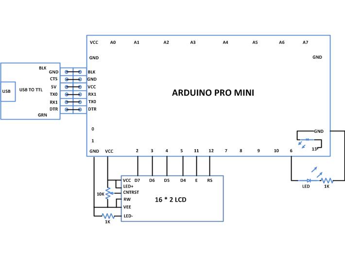
/*================================= EG LABS =======================================

Display smileys animation on a 16*2 LCD along with blinking an LED 

 The circuit:

 * LED attached from pin 5 to ground through a 1K resistor

 LCD:

 * LCD RS pin to digital pin 12

 * LCD Enable pin to digital pin 11

 * LCD D4 pin to digital pin 5

 * LCD D5 pin to digital pin 4

 * LCD D6 pin to digital pin 3

 * LCD D7 pin to digital pin 2

 * LCD R/W pin to ground

 * 10K resistor:

 * ends to +5V and ground

 * wiper to LCD pin 3

 * LED anode attached to digital output 6

 * LED cathode attached to ground through a 1K resistor

//================================= EG LABS =======================================*/

// include the library code:

#include <LiquidCrystal.h>

// initialize the library with the numbers of the interface pins

LiquidCrystal lcd(12, 11, 5, 4, 3, 2);

//----------------- store the custom characters in arrays ---------------------//

byte smile[8] = 

              {

                0b00000,

                0b00000,

                0b01010,

                0b00000,

                0b10001,

                0b01110,

                0b00000,

                0b00000

              };

byte cry[8] = 

              {

                0b00000,

                0b00000,

                0b01010,

                0b01010,

                0b00000,

                0b00000,

                0b01110,

                0b10001

              };       

//----------------- store the custom characters in arrays ---------------------//

// give the LED pin a name:

int led = 6;

int i = 0;

void setup()

{

  //---- create custom characters ----//

  lcd.createChar(1, smile);

  lcd.createChar(2, cry);

  //---- create custom characters ----//

  // initialize the led pin as an output.

  pinMode(led, OUTPUT);

  // set up the lcd's number of columns and rows: 

  lcd.begin(16, 2);

  lcd.print("ENGINEERS GARAGE");

  delay(2000);

}

void loop()

{

  lcd.setCursor(0, 1);

  for(i = 0; i < 16; i ++)

    lcd.write(1);

 //---- blink LED -----//

  digitalWrite(led, HIGH);       

  delay(500);

  digitalWrite(led, LOW);

  delay(200);

   //---- blink LED -----//

  lcd.setCursor(0, 1);

  for(i = 0; i < 16; i ++)

     lcd.write(2);

 //---- blink LED -----//

  digitalWrite(led, HIGH);       

  delay(500);

  digitalWrite(led, LOW);

  delay(200);

  //---- blink LED -----//

}

###


Circuit Diagrams

Circuit-Diagram-Creating-Animation-16×2-LCD-Using-Arduino

Project Components

  • Arduino Pro Mini
  • LCD
  • LED
  • Resistor

Project Video


Filed Under: Arduino
Tagged With: animation, Arduino, lcd
 

Questions related to this article?
👉Ask and discuss on Electro-Tech-Online.com and EDAboard.com forums.


Tell Us What You Think!! Cancel reply

You must be logged in to post a comment.

HAVE A QUESTION?

Have a technical question about an article or other engineering questions? Check out our engineering forums EDABoard.com and Electro-Tech-Online.com where you can get those questions asked and answered by your peers!


Featured Tutorials

  • Introduction to Brain Waves & its Types (Part 1/13)
  • Understanding NeuroSky EEG Chip in Detail (Part 2/13)
  • Performing Experiments with Brainwaves (Part 3/13)
  • Amplification of EEG Signal and Interfacing with Arduino (Part 4/13)
  • Controlling Led brightness using Meditation and attention level (Part 5/13)
  • Control Motor’s Speed using Meditation and Attention Level of Brain (Part 6/13)

Stay Up To Date

Newsletter Signup

Sign up and receive our weekly newsletter for latest Tech articles, Electronics Projects, Tutorial series and other insightful tech content.

EE Training Center Classrooms

EE Classrooms

Recent Articles

  • What are the battery-selection criteria for low-power design?
  • Key factors to optimize power consumption in an embedded device
  • EdgeLock A5000 Secure Authenticator
  • How to interface a DS18B20 temperature sensor with MicroPython’s Onewire driver
  • Introduction to Brain Waves & its Types (Part 1/13)

Most Popular

5G 555 timer circuit 8051 ai Arduino atmega16 automotive avr bluetooth dc motor display Electronic Part Electronic Parts Fujitsu ic infineontechnologies integratedcircuit Intel IoT ir lcd led maximintegratedproducts microchip microchiptechnology Microchip Technology microcontroller microcontrollers mosfet motor powermanagement Raspberry Pi remote renesaselectronics renesaselectronicscorporation Research samsung semiconductor sensor software STMicroelectronics switch Technology vishayintertechnology wireless

RSS EDABOARD.com Discussions

  • Slope compensation ramp calculation for UCC38084
  • Parts storage / inventory best practices and organization
  • Unusual gap shape of ETD59 ferrite core?
  • Vco cadencd
  • WH-LTE-7S1 GSM module and SIM card problem

RSS Electro-Tech-Online.com Discussions

  • surge arresters
  • NOR gate oscillator in LTspice not working
  • HV Diodes
  • intro to PI
  • Very logical explanation on low calue C3
Engineers Garage
  • Analog IC TIps
  • Connector Tips
  • DesignFast
  • EDABoard Forums
  • EE World Online
  • Electro-Tech-Online Forums
  • Microcontroller Tips
  • Power Electronic Tips
  • Sensor Tips
  • Test and Measurement Tips
  • 5G Technology World
  • About Us
  • Contact Us
  • Advertise

Copyright © 2022 WTWH Media LLC. All Rights Reserved. The material on this site may not be reproduced, distributed, transmitted, cached or otherwise used, except with the prior written permission of WTWH Media
Privacy Policy | Advertising | About Us

Search Engineers Garage

  • Projects and Tutorials
    • Electronic Projects
      • 8051
      • Arduino
      • ARM
      • AVR
      • PIC
      • Raspberry pi
      • STM32
    • Tutorials
    • Circuit Design
    • Project Videos
    • Components
  • Articles
    • Tech Articles
    • Insight
    • Invention Stories
    • How to
    • What Is
  • News
    • Electronic Products News
    • DIY Reviews
    • Guest Post
  • Forums
    • EDABoard.com
    • Electro-Tech-Online
    • EG Forum Archive
  • Digi-Key Store
    • Cables, Wires
    • Connectors, Interconnect
    • Discrete
    • Electromechanical
    • Embedded Computers
    • Enclosures, Hardware, Office
    • Integrated Circuits (ICs)
    • Isolators
    • LED/Optoelectronics
    • Passive
    • Power, Circuit Protection
    • Programmers
    • RF, Wireless
    • Semiconductors
    • Sensors, Transducers
    • Test Products
    • Tools
  • EE Resources
    • DesignFast
    • LEAP Awards
    • Oscilloscope Product Finder
    • White Papers
    • Webinars
  • EE Learning Center
    • Design Guides
      • WiFi & the IOT Design Guide
      • Microcontrollers Design Guide
      • State of the Art Inductors Design Guide
  • Women in Engineering