The Raspberry pi is a mini computer which is designed in a single board with all the essential components required for running an operating system. The Raspberry pi board runs on the Broadcom controller chip which is a SoC (System on Chip). This powerful processor and the controller having the peripherals like timers, interrupt controller, GPIO, PCM / I2S, DMA controller, I2C, SPI slave, PWM, UART, USB, graphical processing unit (GPU) which includes VideoCore, MPEG-2 and MPEG-4 and a 512 MB SDRAM makes it a mini-computer. The board is provided with a RCA connector which can be used to connect it directly to a TV screen which is based on PAL and NTSC standard. The board also has a HDMI connector output which can be used to connect the board to a HD TV.
The Raspberrypi board is powerful enough to run large operating systems like Linux, Mac and Windows. Linux operating systems especially Ubuntu is preferred for all kind of programming and development. Since the board capable of generating graphics on standard display screen needs a perfect application using which the programmers can exploit that capability. The ‘QT’ is a widely used platform for creating GUIs in Linux environment. The ‘QT’ is a widely used platform for creating GUIs in Linux environment. Qt is an application which helps in developing the UI framework using the Qt IDE. Qt uses standard C++ but it also supports support many compilers, including the GCC C++ compiler and the Visual Studio suite.
The GUI or graphical user interface makes it easy for the user to control or communicate with the applications which are connected to that particular GUI. The most unavoidable components of a GUI window are ‘buttons’ and this article discusses how to create a button and use it with the help of QT.
In this project the Raspberrypi board is loaded with Ubuntu and is remotely accessed using VNC. The Raspberrypi board is also connected to the internet. Downloading and installing the fourth version, QT4 using commands are already discussed in a previous article. There is another article which discusses about how to start with programming in QT, a hello world program using QT.
Once the installation is complete the user can find them listed under the installed programs for ‘Programming’ as shown in the following image;
Fig. 2: QT Listed In Installed Programs
The list includes “Qt 4 Assistant”, “Qt 4 Designer”, “Qt 4 Linguist” and “Qt Creator”. The “Qt 4 Assistant” is basically provides help in the form of documentations related to the topics in QT. “Qt 4 Designer” is where the user can create a design and save it as a ‘.ui’ file which can then be used in QT projects. The “Qt 4 Linguist” provides a language view of the design created. The “Qt Creator” is where all these things can be done in the same IDE which helps in creating a GUI using QT.
Click on the “Qt Creator” and the following window opens up which includes options for creating a project as explained in the article hello world program using QT.
As soon as a new project is created the “Edit” window of the Qt Creator will open up. Expand the “Forms” where the “mainwindow.ui” can be seen listed. Now double click on the “mainwindow.ui” and the Qt Creator’s “Design” window opens up:
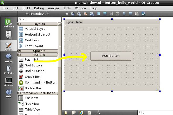
Fig. 3: Drag And Drop ‘Push Button’ QT Creator Window In Ubuntu
Drag and drop a ‘Push Button’ from the list of ‘Buttons’ into the dialogue box as shown in the above image. Right click on the ‘Push Button’ and the text displayed on the button can be modified by selecting the “Change text” option.
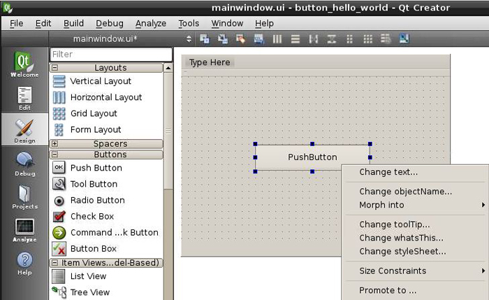
Fig. 4: Editing Text of Push Button In QT Creator Window For GUI In Raspberry Pi
Every component in the designer is represented as an object in the code in the editor and every object has a specific default name also. It is possible to change the name of the object as per the convenience of the user, necessary when using many numbers of buttons or other components. Right click on the ‘Push Button’ and the object name of the button can be modified by selecting the “Change object name” option.
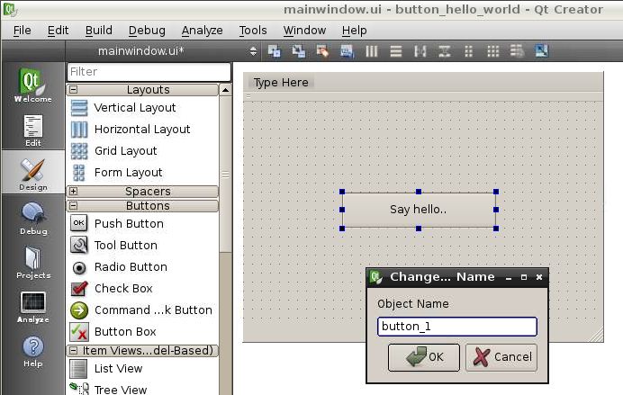
Fig. 5: Changing Object Name And Text In QT Creator Window
Here the object name is modified to “button_1” and the text displayed on the button is changed to “Say hello”. As soon as the object name is changed the same change can be visible as marked in the following image:
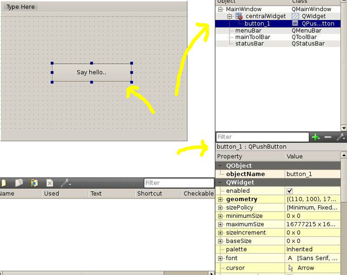
Fig. 6: Push Button Name Changed To Say Hello
In the following steps how to assign a particular function to the button is discussed. There are terms called ‘Signals’ and ‘Slots’. Slots are basically functions which are associated with an object and the Signals are send to execute those functions whenever the object is enabled. For example whenever the user clicks on a button a Signal will be send to the corresponding Slot function.
To create a Slot and Signal corresponding to an object just right click on the button and select the option “Go to Slot”.
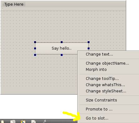
Fig. 7: Creating Slot For Object Button To Assign Function With QT
The user will be provided with a list of Signals corresponding to that Push Button type object. Since the button is commonly used for clicking, here the signal ‘clicked ()’ has been selected.
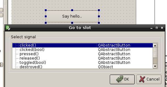
Fig. 8: Creating Signal For Object Button To Execute Function With QT
Once clicked on the “OK” button it will instantly direct the user to the Editor window where the corresponding Slot can be visible in the code, here “_on_button_1_clicked ()”
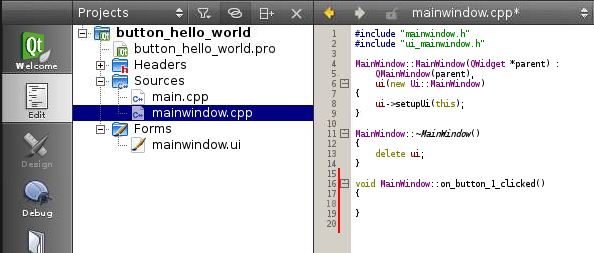
Fig. 9: Slot Visible In Code Of Editor Window
This function will be called whenever the button object named “button_1 is clicked. Just to test it the user can write a simple printf () statement as shown in the following image, don’t forget to add the <stdio.h> header file.
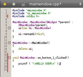
Fig. 10: Testing The Code With Print f Command
The coding is finished with that and now save the project using “File >> Save All”.
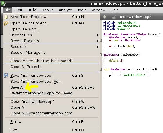
Fig. 11: Saving The Project Using File From QT Creator Tool Bar
Build the code and run it as explained in the article hello world program using QT.
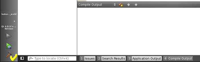
Fig. 12: Build Code And Run Using QT
As the GUI runs it prints the string “HELLO WORLD” each and every time the button “Say Hello” is clicked.
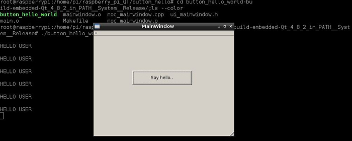
Fig. 13: “HELLO WORLD” Printed As GUI Executes Command
Filed Under: Raspberry pi

Questions related to this article?
👉Ask and discuss on Electro-Tech-Online.com and EDAboard.com forums.
Tell Us What You Think!!
You must be logged in to post a comment.