Engineers Garage

  • Electronics Projects and Tutorials
    • Electronic Projects
      • Arduino Projects
      • AVR
      • Raspberry pi
      • ESP8266
      • BeagleBone
      • 8051 Microcontroller
      • ARM
      • PIC Microcontroller
      • STM32
    • Tutorials
      • Audio Electronics
      • Battery Management
      • Brainwave
      • Electric Vehicles
      • EMI/EMC/RFI
      • Hardware Filters
      • IoT tutorials
      • Power Tutorials
      • Python
      • Sensors
      • USB
      • VHDL
    • Circuit Design
    • Project Videos
    • Components
  • Articles
    • Tech Articles
    • Insight
    • Invention Stories
    • How to
    • What Is
  • News
    • Electronic Product News
    • Business News
    • Company/Start-up News
    • DIY Reviews
    • Guest Post
  • Forums
    • EDABoard.com
    • Electro-Tech-Online
    • EG Forum Archive
  • DigiKey Store
    • Cables, Wires
    • Connectors, Interconnect
    • Discrete
    • Electromechanical
    • Embedded Computers
    • Enclosures, Hardware, Office
    • Integrated Circuits (ICs)
    • Isolators
    • LED/Optoelectronics
    • Passive
    • Power, Circuit Protection
    • Programmers
    • RF, Wireless
    • Semiconductors
    • Sensors, Transducers
    • Test Products
    • Tools
  • Learn
    • eBooks/Tech Tips
    • Design Guides
    • Learning Center
    • Tech Toolboxes
    • Webinars & Digital Events
  • Resources
    • Digital Issues
    • EE Training Days
    • LEAP Awards
    • Podcasts
    • Webinars / Digital Events
    • White Papers
    • Engineering Diversity & Inclusion
    • DesignFast
  • Guest Post Guidelines
  • Advertise
  • Subscribe

How to design a regulated power supply

By Ashutosh Bhatt November 13, 2020

The performance of every electronic system or electronic circuit depends upon the power supply that energizes the circuit or system. It provides the required current to the circuit. Any disturbance noise in this power supply can cause problems in the working or operation of the circuit. If there is any deviation in this power supply level the circuit may not work properly. The accuracy and precision of circuit operation depends upon it.  In some of the circuits all the calibration is done at this voltage level. So all these calibrations become false if there is a fluctuation in supply level. 

There are two types of power supplies

1)      Unregulated power supply

2)      Regulated power supply

Unregulated supply is used in some circuits where there is no much change in the required load current. The load current remains fixed or deviation is very less. Because in such supply

1)      The output voltage reduces as load current increases

2)      The ripple in output voltage increases as load current increases

So this kind of supply can not be used where there is a noticeable change in load current frequently. But although many circuits work on unregulated supply because it requires very few components and design is also very simple. Also, some fluctuation in supply level can be tolerated due to load current change. The regulated power supply is required in digital circuits, the circuits in which the components can not tolerate even 1% change in supply level like microcontroller, micro processor etc.

So here I am giving the steps to designing a regulated power supply including which components should be chosen to have required regulated output voltage with required current. The procedure requires calculations based on some designing equations, some assumptions and approximations that we must take during designing.

Consider the following notification

Erms     :           rms value of AC voltage (transformer secondary voltage)

Em       :           max value of AC voltage

VdcNL   :           no load DC voltage

VdcFL    :           full load DC voltage

Ro        :           internal resistance

 IL         :           full load output current

VLmin   :           minimum output voltage from unregulated supply

Vrms     :           rms value of ripple

?Vo     :           pick ripple voltage 

Following equations – relations are used in designing power supply

VdcNL = Em =  Erms / 1.41

VdcFL = VdcNL – Ro IL

?Vo = IL / (200 C)

?Vo = 3.5 Vrms

VLmin = VdcFL –  ?Vo / 2

So let us start designing

AIM: design regulated power supply for 5 V @ 1 A

Procedure:

We have to design 2 separate sections

      1) Regulated section

      2) Unregulated section

Design of Regulated section –

Step 1: select voltage regulator chip

Because we are designing a regulated power supply, we need a voltage regulator chip. There are so many voltage regulator chips available. They are broadly classified into different categories based on

1)      Polarity : positive, negative or dual

2)      Fixed output or variable output

3)      Required output current from 0.1 A – 5 A

Here we require fixed and positive supply with current capacity 1 A. So we have to choose LM7805 voltage regulator chip.

Step 2: input – output capacitive filter

Input capacitor is required to suppress or minimize any ripple or variation in input applied to the regulator chip. Its typical value is 0.33µF as specified in the datasheet. This can be neglected if the regulator chip is connected very close to the filtering capacitor of the rectifier. It is only required when the distance between rectifier output and regulator input. 

Output capacitor is required to suppress any spike or glitch in fixed output voltage that may occur due to transient change in AC input. Its typical value is 0.1 µF as specified in the datasheet.  

This completes the design of the regulated section.

Design of Unregulated section –

It feeds the regulated section. Its rectifier + filter. The most required thing is the input given by this section to the regulated section must be at least 3 V higher than the required output voltage. This is known as ‘headroom’ for regulator chip. This gives us

VLmin = Vop + headroom

=          5 + 3

=          8 V

For this section, we have to select the transformer, diode, and capacitor.

Step 3: selecting capacitor

Let us assume the capacitor is 1000 µF electrolyte capacitor. We need to find out its working DC voltage WLDC, but that depends upon VdcNL as

WLDC = VdcNL + 20% VdcNL

So after finding VdcNL we can calculate it.

From this capacitor value we can find ?Vo as

?Vo = IL / (200 C)

So for IL = 1 A and C = 1000 µF

         ?Vo = 1 / 200×1000×10-6

                = 5 V

From ?Vo and VLmin, VdcFL can be calculated as

                 VdcFL = VLmin + ?Vo / 2

                                                            = 8 + 5/2

                                                            = 10.5 V

VdcFL is related with VdcNL as

                 VdcNL = VdcFL + Ro IL

Ro value is between 6? to 10?. Assuming Ro as 8?

                  VdcNL = 10.5 + 8×1

                                                             = 18.5 V

Now calculate required WLDC

WLDC = VdcNL + 20% VdcNL

                                                                  = 18.5 + 3.7

                                                                  = 22.2 V

Always we have to go for higher value than this. So choose capacitor with WLDC of 25 V. So finally our capacitor is

C = 1000 µF @ 25 V

Step 4: selecting diode

Selecting a diode means finding the current capacity and PIV of the diode.

1.      Current capacity IC > IL that means Ic can be 1 A or more

2.      PIV = VdcNL + 20% VdcNL = 22.2. again going for higher value that is 25 V

Finally required diodes are with


D = 1A @ 25V

All the diodes of series 1N4004, 1N4007, 1N4009 satisfies these criteria.

Step 5: selecting a transformer

The rms value of transformer output is given by

                   Erms  = Em / 1.41

But Em = VdcNL.,  So

                                                   Erms  = VdcNL / 1.41

                                                            = 18.5 / 1.41

                                                            = 13.12 VAC

So we may select either

  1. 1)      Center tap transformer of 9 –  0 – 9 or 7 .5 – 0 – 7.5 secondary voltage
  2. 2)      Transformer Without center tapping either 0 – 15 or 0 – 18 secondary voltage

The current rating for the secondary of the transformer should be at least 1.8 IL. That means the current rating can be 2 A.

Finally select a transformer with

T = 230 / 15 VAC @ 2A

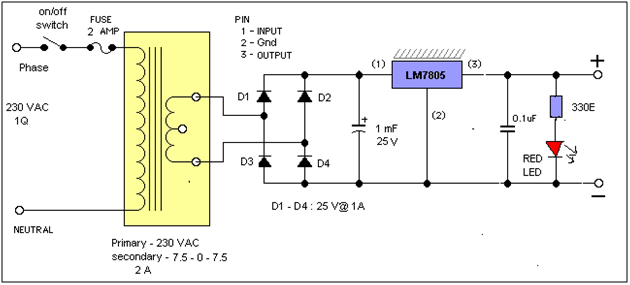
Schematic of final design is as shown in the circuit diagram tab. 


You may also like:


  • What are the top technologies enabling M2M in 2023?

  • What are different types of industrial robots?

  • What is LoRa and LoRaWAN?

  • What are LoRa gateways and what types are available?

  • How does LoRa modulation enable long-range communication?

  • What battery chemistries are used in electric vehicles?

Circuit Diagrams

fixed-power-supply


Filed Under: Circuit Design, Electronic Projects
Tagged With: regulated power supply
 

Next Article

← Previous Article
Next Article →

Questions related to this article?
👉Ask and discuss on EDAboard.com and Electro-Tech-Online.com forums.


Tell Us What You Think!! Cancel reply

You must be logged in to post a comment.

EE TECH TOOLBOX

“ee
Tech Toolbox: Internet of Things
Explore practical strategies for minimizing attack surfaces, managing memory efficiently, and securing firmware. Download now to ensure your IoT implementations remain secure, efficient, and future-ready.

EE Learning Center

EE Learning Center
“engineers
EXPAND YOUR KNOWLEDGE AND STAY CONNECTED
Get the latest info on technologies, tools and strategies for EE professionals.

HAVE A QUESTION?

Have a technical question about an article or other engineering questions? Check out our engineering forums EDABoard.com and Electro-Tech-Online.com where you can get those questions asked and answered by your peers!


RSS EDABOARD.com Discussions

  • Engineer's own PCB layout software guide?
  • LVS Mismatch Error in Simple Layout
  • Does mobility carrier ratio changes with Wn? (0.18um) inverter design
  • Lightbox circuit help
  • 12VAC to 12VDC 5A on 250ft 12AWG

RSS Electro-Tech-Online.com Discussions

  • Lightbox circuit
  • Fuel Auto Shutoff
  • Kawai KDP 80 Electronic Piano Dead
  • Python help with keystroke entries
  • Do resistors fail like dominoes?

Featured – Designing of Audio Amplifiers part 9 series

  • Basics of Audio Amplifier – 1/9
  • Designing 250 Milli Watt Audio Power Amplifier – 2/9
  • Designing 1 Watt Audio Power Amplifier – 3/9
  • Designing a Bass Boost Amplifier – 4/9
  • Designing a 6 Watt Car Audio Amplifier – 5/9
  • Design a low power amplifier for headphones- 6/9

Recent Articles

  • ITG Electronics releases gate drive transformers with 200 – 450 V DC capability
  • Stackpole introduces HCJ jumpers with 70.7 amp continuous current capability
  • Infineon releases MCU with 128K flash and multi-sense capabilities
  • ST introduces 600V GaN gate drivers with 300 ns start-up time
  • ABLIC releases S-19116 automotive voltage detector with 6.8μs response time

EE ENGINEERING TRAINING DAYS

engineering

Submit a Guest Post

submit a guest post
Engineers Garage
  • Analog IC TIps
  • Connector Tips
  • Battery Power Tips
  • DesignFast
  • EDABoard Forums
  • EE World Online
  • Electro-Tech-Online Forums
  • EV Engineering
  • Microcontroller Tips
  • Power Electronic Tips
  • Sensor Tips
  • Test and Measurement Tips
  • 5G Technology World
  • Subscribe to our newsletter
  • About Us
  • Contact Us
  • Advertise

Copyright © 2025 WTWH Media LLC. All Rights Reserved. The material on this site may not be reproduced, distributed, transmitted, cached or otherwise used, except with the prior written permission of WTWH Media
Privacy Policy

Search Engineers Garage

  • Electronics Projects and Tutorials
    • Electronic Projects
      • Arduino Projects
      • AVR
      • Raspberry pi
      • ESP8266
      • BeagleBone
      • 8051 Microcontroller
      • ARM
      • PIC Microcontroller
      • STM32
    • Tutorials
      • Audio Electronics
      • Battery Management
      • Brainwave
      • Electric Vehicles
      • EMI/EMC/RFI
      • Hardware Filters
      • IoT tutorials
      • Power Tutorials
      • Python
      • Sensors
      • USB
      • VHDL
    • Circuit Design
    • Project Videos
    • Components
  • Articles
    • Tech Articles
    • Insight
    • Invention Stories
    • How to
    • What Is
  • News
    • Electronic Product News
    • Business News
    • Company/Start-up News
    • DIY Reviews
    • Guest Post
  • Forums
    • EDABoard.com
    • Electro-Tech-Online
    • EG Forum Archive
  • DigiKey Store
    • Cables, Wires
    • Connectors, Interconnect
    • Discrete
    • Electromechanical
    • Embedded Computers
    • Enclosures, Hardware, Office
    • Integrated Circuits (ICs)
    • Isolators
    • LED/Optoelectronics
    • Passive
    • Power, Circuit Protection
    • Programmers
    • RF, Wireless
    • Semiconductors
    • Sensors, Transducers
    • Test Products
    • Tools
  • Learn
    • eBooks/Tech Tips
    • Design Guides
    • Learning Center
    • Tech Toolboxes
    • Webinars & Digital Events
  • Resources
    • Digital Issues
    • EE Training Days
    • LEAP Awards
    • Podcasts
    • Webinars / Digital Events
    • White Papers
    • Engineering Diversity & Inclusion
    • DesignFast
  • Guest Post Guidelines
  • Advertise
  • Subscribe