Engineers Garage

  • Projects and Tutorials
    • Electronic Projects
      • 8051
      • Arduino
      • ARM
      • AVR
      • PIC
      • Raspberry pi
      • STM32
    • Tutorials
    • Circuit Design
    • Project Videos
    • Components
  • Articles
    • Tech Articles
    • Insight
    • Invention Stories
    • How to
    • What Is
  • News
    • Electronic Products News
    • DIY Reviews
    • Guest Post
  • Forums
    • EDABoard.com
    • Electro-Tech-Online
    • EG Forum Archive
  • Digi-Key Store
    • Cables, Wires
    • Connectors, Interconnect
    • Discrete
    • Electromechanical
    • Embedded Computers
    • Enclosures, Hardware, Office
    • Integrated Circuits (ICs)
    • Isolators
    • LED/Optoelectronics
    • Passive
    • Power, Circuit Protection
    • Programmers
    • RF, Wireless
    • Semiconductors
    • Sensors, Transducers
    • Test Products
    • Tools
  • EE Resources
    • DesignFast
    • LEAP Awards
    • Oscilloscope Product Finder
    • White Papers
    • Webinars
  • EE Learning Center
    • Design Guides
      • WiFi & the IOT Design Guide
      • Microcontrollers Design Guide
      • State of the Art Inductors Design Guide
  • Women in Engineering

How to Design a Variable Regulated Power Supply

By Ashutosh Bhatt


The electronics devices works in dc power supply comes with different voltage specifications. Some devices works in battery power with voltages ranging from 1.5V to 9V, but majority of the devices can be directly plugged into a power plug. Such devices have a built in AC to low voltage DC converter inside it and the voltage output of that converter will be corresponding to the design of the entire circuit. The design of a circuit actually begins with considering the value of the voltage which will be supplied to it.

The circuits which work in 5V power supply are most common which contains 5V TTL devices, but there is other category of TTL devices which works in 3.3V supply. Apart from these two categories there are CMOS based circuits and there is all kind of analog circuits which are designed to work on different voltages. Those who are interested in working with all these kind of circuits should have a variable power supply source. Since most of the electronic designs demands regulated power supply the variable power source should be regulated also. This article discusses how to design a Variable Regulated Power Supply.

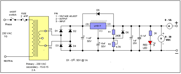
AIM: design variable regulated power supply from 1V to 25 V @ 1A

We shall follow same procedure followed in Regulated Power Supply.
Design of Regulated section:-
Step 1: Selecting regulator chip:
Because here we need variable supply we shall use LM317. The equation for output voltage is
Vo = 1.25 (1 + R2 / R1)
In above equation R1 is fixed as 240?. So by varying R2 we can change output voltage. Because required o/p voltage is 25 V, we shall calculate required value of R2 as
R2 = (Vo/1.25 – 1) × R1
= (25 / 1.25 – 1) × 240
= 4560 ?
So we shall use 4.7 K ? potentiometer
Step 2: Selecting filter capacitor:
We may neglect input capacitor filter. For output we can use either 0.1 µF or 1 µF capacitor Output capacitor is required to suppress any spike or glitch in fixed output voltage that may occur due to transient change in AC input. 
Design of unregulated section –
If we follow same calculations as given in previous design then we have following values
VLmin = 28 V
Vo = 5 V
VdcFL = 30.5
VdcNL = 38.5
From these we shall find out transformer, capacitor and diode ratings
 Step 3: Selecting transformer:
Erms  = VdcNL / 1.41
                                                                                = 38.5 / 1.41
                                                            = 27.30 VAC
So we may select Center tap transformer of 15 –  0 – 15. Current rating for secondary of transformer should be at least 1.8 IL. That means the current rating can be 2 A.
Finally select transformer with
T = 230 / 30 VAC @ 2A
Step 4: Selecting diode
Selecting diode means finding current capacity and PIV of diode.
1.      Current capacity IC > IL that means Ic can be 1 A or more
2.      PIV = VdcNL + 20% VdcNL = 46.2. again going for higher value that is 50 V
Finally required diodes are with
D = 1A @ 50V
Step 5: Selecting capacitor
Assumed value of capacitor is C = 1000 µF.
WLDC = VdcNL + 20% VdcNL = 46.2. again going for higher value that is 50 V
Finally required capacitor is with
C = 1000 µF @ 50V
 If you want to have indication of output voltage and current then you can connect voltmeter and ammeter of analog scale.
·         Voltage meter of range 0 – 30 V in parallel
·         Ammeter of range 0 – 1A in series
The schematic is as shown in Circuit Diagram Tab2. 


Circuit Diagrams

variable-power-supply-design1_0
variable-power-supply-design2


Filed Under: Electronic Projects
Tagged With: variable power supply
 

Questions related to this article?
👉Ask and discuss on Electro-Tech-Online.com and EDAboard.com forums.


Tell Us What You Think!! Cancel reply

You must be logged in to post a comment.

HAVE A QUESTION?

Have a technical question about an article or other engineering questions? Check out our engineering forums EDABoard.com and Electro-Tech-Online.com where you can get those questions asked and answered by your peers!


Featured Tutorials

  • Introduction to Brain Waves & its Types (Part 1/13)
  • Understanding NeuroSky EEG Chip in Detail (Part 2/13)
  • Performing Experiments with Brainwaves (Part 3/13)
  • Amplification of EEG Signal and Interfacing with Arduino (Part 4/13)
  • Controlling Led brightness using Meditation and attention level (Part 5/13)
  • Control Motor’s Speed using Meditation and Attention Level of Brain (Part 6/13)

Stay Up To Date

Newsletter Signup

Sign up and receive our weekly newsletter for latest Tech articles, Electronics Projects, Tutorial series and other insightful tech content.

EE Training Center Classrooms

EE Classrooms

Recent Articles

  • What is a loop calibrator? 
  • What are the battery-selection criteria for low-power design?
  • Key factors to optimize power consumption in an embedded device
  • EdgeLock A5000 Secure Authenticator
  • How to interface a DS18B20 temperature sensor with MicroPython’s Onewire driver

Most Popular

5G 555 timer circuit 8051 ai Arduino atmega16 automotive avr bluetooth dc motor display Electronic Part Electronic Parts Fujitsu ic infineontechnologies integratedcircuit Intel IoT ir lcd led maximintegratedproducts microchip microchiptechnology Microchip Technology microcontroller microcontrollers mosfet motor powermanagement Raspberry Pi remote renesaselectronics renesaselectronicscorporation Research samsung semiconductor sensor software STMicroelectronics switch Technology vishayintertechnology wireless

RSS EDABOARD.com Discussions

  • Passive Harmonics Filter
  • file edit
  • RCF Subwoofer Amplifier PIC16F870-I/SP please help me about hex code
  • Active Balun Design
  • What was before microcontrollers ?

RSS Electro-Tech-Online.com Discussions

  • Control Bare LCD With ATmega328p
  • Need a ducted soldering fan for solder smoke extraction
  • Identify a circuit.
  • Sla ir li ion
  • Question about ultrasonic mist maker
Engineers Garage
  • Analog IC TIps
  • Connector Tips
  • DesignFast
  • EDABoard Forums
  • EE World Online
  • Electro-Tech-Online Forums
  • Microcontroller Tips
  • Power Electronic Tips
  • Sensor Tips
  • Test and Measurement Tips
  • 5G Technology World
  • About Us
  • Contact Us
  • Advertise

Copyright © 2022 WTWH Media LLC. All Rights Reserved. The material on this site may not be reproduced, distributed, transmitted, cached or otherwise used, except with the prior written permission of WTWH Media
Privacy Policy | Advertising | About Us

Search Engineers Garage

  • Projects and Tutorials
    • Electronic Projects
      • 8051
      • Arduino
      • ARM
      • AVR
      • PIC
      • Raspberry pi
      • STM32
    • Tutorials
    • Circuit Design
    • Project Videos
    • Components
  • Articles
    • Tech Articles
    • Insight
    • Invention Stories
    • How to
    • What Is
  • News
    • Electronic Products News
    • DIY Reviews
    • Guest Post
  • Forums
    • EDABoard.com
    • Electro-Tech-Online
    • EG Forum Archive
  • Digi-Key Store
    • Cables, Wires
    • Connectors, Interconnect
    • Discrete
    • Electromechanical
    • Embedded Computers
    • Enclosures, Hardware, Office
    • Integrated Circuits (ICs)
    • Isolators
    • LED/Optoelectronics
    • Passive
    • Power, Circuit Protection
    • Programmers
    • RF, Wireless
    • Semiconductors
    • Sensors, Transducers
    • Test Products
    • Tools
  • EE Resources
    • DesignFast
    • LEAP Awards
    • Oscilloscope Product Finder
    • White Papers
    • Webinars
  • EE Learning Center
    • Design Guides
      • WiFi & the IOT Design Guide
      • Microcontrollers Design Guide
      • State of the Art Inductors Design Guide
  • Women in Engineering