Engineers Garage

  • Projects and Tutorials
    • Electronic Projects
      • 8051
      • Arduino
      • ARM
      • AVR
      • PIC
      • Raspberry pi
      • STM32
    • Tutorials
    • Circuit Design
    • Project Videos
    • Components
  • Articles
    • Tech Articles
    • Insight
    • Invention Stories
    • How to
    • What Is
  • News
    • Electronic Products News
    • DIY Reviews
    • Guest Post
  • Forums
    • EDABoard.com
    • Electro-Tech-Online
    • EG Forum Archive
  • Digi-Key Store
    • Cables, Wires
    • Connectors, Interconnect
    • Discrete
    • Electromechanical
    • Embedded Computers
    • Enclosures, Hardware, Office
    • Integrated Circuits (ICs)
    • Isolators
    • LED/Optoelectronics
    • Passive
    • Power, Circuit Protection
    • Programmers
    • RF, Wireless
    • Semiconductors
    • Sensors, Transducers
    • Test Products
    • Tools
  • EE Resources
    • DesignFast
    • LEAP Awards
    • Oscilloscope Product Finder
    • White Papers
    • Webinars
  • EE Learning Center
    • Design Guides
      • WiFi & the IOT Design Guide
      • Microcontrollers Design Guide
      • State of the Art Inductors Design Guide
  • Women in Engineering

How to detect Variation in EEG Signals in the form of LEDs using LM3915 (Part 10/13)

By Arpit jain

How to detect Variation in EEG Signals in the form of LEDs using LM3915

SUMMARY

After taking on the experiment of appliance control with relay, I am thinking of analyzing the EEG wave produced by the brain and see the variations in the form of LEDs. It would be really nice if we could see the variations of our EEG signals clearly in the form of some LED patterns so as to analyse how much variation it is producing by various thinking processes. Let’s get started.
 
Image showing EEG Signals Displayed as LEd Light Variation
 
Fig. 1: Image showing EEG Signals Displayed as LEd Light Variation
DESCRIPTION
 
I decided to use LM3915 IC which can convert the analog voltage into the digitized form from 1 to 10 and turn as many number of LEDs as the digitized value. It can also be termed as ADC (Analog to Digital Convertor). By analyzing our wave on CR, we have seen that the voltage range is upto 1V. So, we set the reference of the LM3915 to 1V. By doing this we convey to the LM3915 that 0v means 0 LEDs and 1V means 10 LEDS. So now let’s say 4 LEDs are glowing, this means that the voltage is near to 0.4 V. We have just sent the analog EEG signal directly to the LM3915 IC and attached LEDs at the other end for the result. Please watch the video for the experiment. 
 
Image showing EEG Signals Displayed as LEd Light Variation
 
Fig. 2; Image showing EEG Signals displayed as LEd Light Variation
 
We can conclude that the waves are not very stable in magnitude. I also believe that there will be some noise which has been transferred to the 3915 IC. This can also be seen that many times the LEDs go to full magnitude and remain there, which is not the case when checked with CRO. This can be due to the noise as we have just soldered the wire and it is open and long too. Anyways, Brain waves are very interesting and I am still searching to find some patterns in them to perform more such experiments. By this experiment, I have found the variation in our EEG and the effect of noise. I am assuming this as a noise but it can be something else.
 
Block Diagram of MindFlex Brainwave Sensor based EEG Signal LED Indicator
 
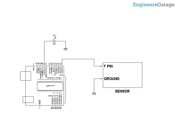
Fig. 3: Block Diagram of MindFlex Brainwave Sensor based EEG Signal LED Indicator
 
Hardware:  Please find the attached circuit diagram of the connections that are to be established.  We have soldered a pin from the EEG pin of the Mindflex sensor and inserted the output of the EEG pin to that of input of the LM3915. Moreover, we have also set the reference voltage to 1V as our EEG signals will not cross this value. For setting 1V, we are using the resistor network. Though we can use 10 LEDs with the 3915IC but here we will only use 4 LEDs just to see the variations and change of our EEG wave. 
 
Softwares: There is no coding done in this experiment.
 
Few points to Note:
 
Try to shield this wire and also make sure that the references probes are correctly connected. You can try this experiment and share your feedback with us. In the next experiment we will try to change the color of the RGB LED.


Project Source Code

###

//Program to 

/*
 Fading
 
 This example shows how to fade an LED using the analogWrite() function.
 
 The circuit:
 * LED attached from digital pin 9 to ground.
 
 Created 1 Nov 2008
 By David A. Mellis
 modified 30 Aug 2011
 By Tom Igoe
 
 http://arduino.cc/en/Tutorial/Fading
 
 This example code is in the public domain.
 
 */
 
 
int ledPin = 9;    // LED connected to digital pin 9
 
void setup() {
  // nothing happens in setup
  //analogWrite(ledPin, 20);
    // wait for 30 milliseconds to see the dimming effect
    //delay(2000);
}
 
void loop() {
  // fade in from min to max in increments of 5 points:
  analogWrite(ledPin, 20);
  
  /*
  for (int fadeValue = 0 ; fadeValue <= 150; fadeValue += 3) {
    // sets the value (range from 0 to 255):
    analogWrite(ledPin, fadeValue);
    // wait for 30 milliseconds to see the dimming effect
    delay(1000);
  }
  delay(1000);
  
  for (int fadeValue = 160 ; fadeValue >= 50; fadeValue -= 10) {
    // sets the value (range from 0 to 255):
    analogWrite(ledPin, fadeValue);
    // wait for 30 milliseconds to see the dimming effect
    delay(60);
  }
  delay(1000);
   for (int fadeValue = 50 ; fadeValue <= 160; fadeValue += 5) {
    // sets the value (range from 0 to 255):
    analogWrite(ledPin, fadeValue);
    // wait for 30 milliseconds to see the dimming effect
    delay(60);
  }
  delay(1000);
   
   for (int fadeValue = 100 ; fadeValue <= 180; fadeValue += 5) {
    // sets the value (range from 0 to 255):
    analogWrite(ledPin, fadeValue);
    // wait for 30 milliseconds to see the dimming effect
   delay(60);
  }
  delay(1000);
  // fade out from max to min in increments of 5 points:


*/  
}


###


Circuit Diagrams

Circuit-Diagram-MindFlex-Brainwave-Sensor-EEG-Signal-LED-Indicator

Project Video


Filed Under: Electronic Projects


Questions related to this article?
👉Ask and discuss on Electro-Tech-Online.com and EDAboard.com forums.


Tell Us What You Think!! Cancel reply

You must be logged in to post a comment.

HAVE A QUESTION?

Have a technical question about an article or other engineering questions? Check out our engineering forums EDABoard.com and Electro-Tech-Online.com where you can get those questions asked and answered by your peers!


Featured Tutorials

  • Introduction to Brain Waves & its Types (Part 1/13)
  • Understanding NeuroSky EEG Chip in Detail (Part 2/13)
  • Performing Experiments with Brainwaves (Part 3/13)
  • Amplification of EEG Signal and Interfacing with Arduino (Part 4/13)
  • Controlling Led brightness using Meditation and attention level (Part 5/13)
  • Control Motor’s Speed using Meditation and Attention Level of Brain (Part 6/13)

Stay Up To Date

Newsletter Signup

Sign up and receive our weekly newsletter for latest Tech articles, Electronics Projects, Tutorial series and other insightful tech content.

EE Training Center Classrooms

EE Classrooms

Recent Articles

  • What are the battery-selection criteria for low-power design?
  • Key factors to optimize power consumption in an embedded device
  • EdgeLock A5000 Secure Authenticator
  • How to interface a DS18B20 temperature sensor with MicroPython’s Onewire driver
  • Introduction to Brain Waves & its Types (Part 1/13)

Most Popular

5G 555 timer circuit 8051 ai Arduino atmega16 automotive avr bluetooth dc motor display Electronic Part Electronic Parts Fujitsu ic infineontechnologies integratedcircuit Intel IoT ir lcd led maximintegratedproducts microchip microchiptechnology Microchip Technology microcontroller microcontrollers mosfet motor powermanagement Raspberry Pi remote renesaselectronics renesaselectronicscorporation Research samsung semiconductor sensor software STMicroelectronics switch Technology vishayintertechnology wireless

RSS EDABOARD.com Discussions

  • Fpga wake up
  • Code Optimization
  • Avalanche Pulser
  • Pull up via GPIO
  • Poly Spacing Effect

RSS Electro-Tech-Online.com Discussions

  • Someone please explain how this BMS board is supposed to work?
  • HV Diodes
  • Question about ultrasonic mist maker
  • DIY bluetooth speaker
  • Disabled son needs advice please
Engineers Garage
  • Analog IC TIps
  • Connector Tips
  • DesignFast
  • EDABoard Forums
  • EE World Online
  • Electro-Tech-Online Forums
  • Microcontroller Tips
  • Power Electronic Tips
  • Sensor Tips
  • Test and Measurement Tips
  • 5G Technology World
  • About Us
  • Contact Us
  • Advertise

Copyright © 2022 WTWH Media LLC. All Rights Reserved. The material on this site may not be reproduced, distributed, transmitted, cached or otherwise used, except with the prior written permission of WTWH Media
Privacy Policy | Advertising | About Us

Search Engineers Garage

  • Projects and Tutorials
    • Electronic Projects
      • 8051
      • Arduino
      • ARM
      • AVR
      • PIC
      • Raspberry pi
      • STM32
    • Tutorials
    • Circuit Design
    • Project Videos
    • Components
  • Articles
    • Tech Articles
    • Insight
    • Invention Stories
    • How to
    • What Is
  • News
    • Electronic Products News
    • DIY Reviews
    • Guest Post
  • Forums
    • EDABoard.com
    • Electro-Tech-Online
    • EG Forum Archive
  • Digi-Key Store
    • Cables, Wires
    • Connectors, Interconnect
    • Discrete
    • Electromechanical
    • Embedded Computers
    • Enclosures, Hardware, Office
    • Integrated Circuits (ICs)
    • Isolators
    • LED/Optoelectronics
    • Passive
    • Power, Circuit Protection
    • Programmers
    • RF, Wireless
    • Semiconductors
    • Sensors, Transducers
    • Test Products
    • Tools
  • EE Resources
    • DesignFast
    • LEAP Awards
    • Oscilloscope Product Finder
    • White Papers
    • Webinars
  • EE Learning Center
    • Design Guides
      • WiFi & the IOT Design Guide
      • Microcontrollers Design Guide
      • State of the Art Inductors Design Guide
  • Women in Engineering