In Part 1 of this series, we learned how to interface an organic light-emitting diode (OLED) display, using analog voltage (a potentiometer), with Arduino.
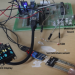
In Part 2, we covered how to present data from an analog sensor — specifically, a light-dependent resistor (LDR) and soil moisture sensor — on an OLED display.
In Part 3, we explained how to present data from the digital sensor DHT11, which is for temperature and humidity, also on an OLED display.
In Part 4, this final article of this series, we’ll continue to present data on an OLED display. This time, we’ll use the ultrasonic distance-measurement (UDM) sensor, HC-SR04. It measures the distance between it and an object using ultrasonic pulses.
Refer to Part I to review the basics on how to interface an OLED with Arduino for the below project.
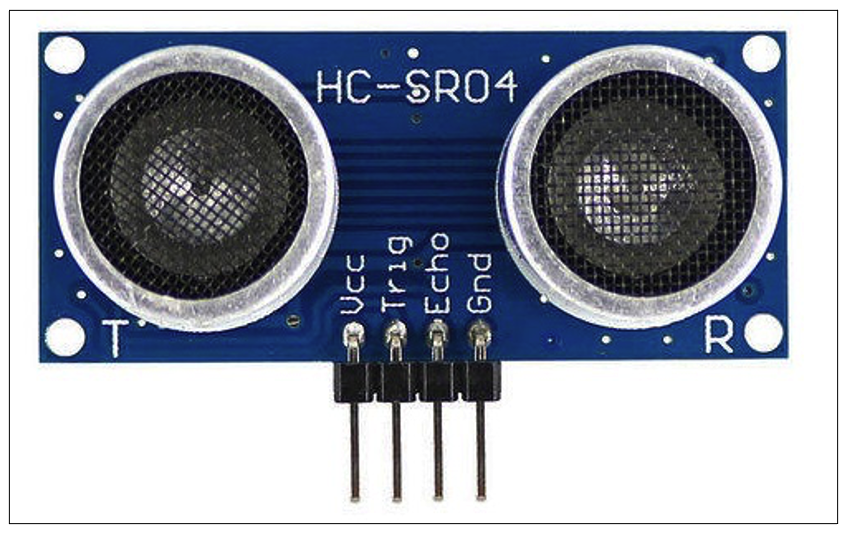
The ultrasonic distance measurement (UDM) sensor, HC-SR04.
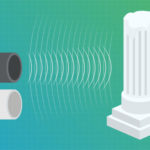
The UDM sensor is extensively used for short or medium-range distance measurement. It’s also used as a proximity sensor for object detection. It works on the principle of RADAR (radio detection and ranging), a detection system that uses radio waves to determine distance.
This sensor transmits tracks pulses of ultrasonic sound, detecting reflected pulses from any object. It calculates the distance by measuring the total time taken by pulses to reflect from a given object.
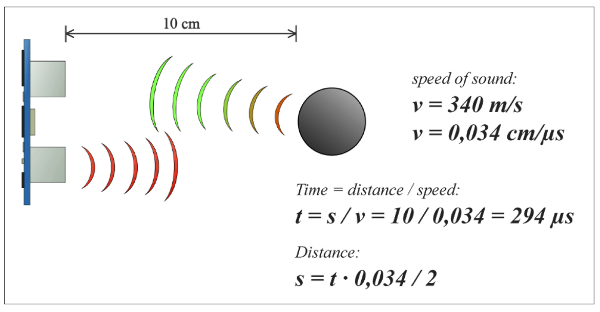
How the UDM sensor operates.
The sensor generates a pulse-width modulation (PWM) output. PWM is a way to control analog devices with a digital output. In this case, the output pulse width varies based on the distance of the object.
So, to measure the distance from a given object, the host device (a microcontroller) measures the width of the output pulse from the sensor.
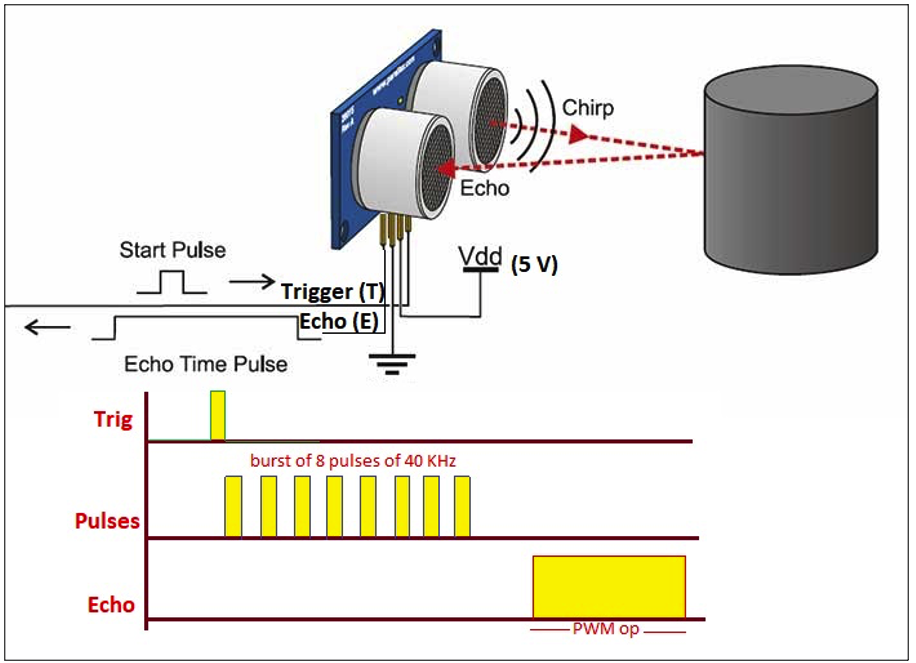
The UDM sensor at work.
The UDM sensor has one trigger (Tr) input pin and one Echo (E) output pin. The trigger pin is given a short duration trigger pulse (10 us). When the trigger is activated, the transmitter projects eight pulses of an ultrasonic sound of about 40 kHz.
These pulses will hit any object in range (as shown in the above diagram, which reflects them. The reflected pulses are detected by the receiver and, as per the time duration (pulse transmitted and pulse received), the sensor provides a PWM output via the Echo (E) pin.
These are the features of the UDM sensor, HC SR04:
- Operates on an ultrasonic frequency of 40 kHz
- Distance measuring range – 1 to 400 cm
- Resolution – 1 cm
- Object detection aperture angle – 30o (-15o to +15o on either side)
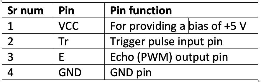
The UDM sensor pins and pin functions
To interface the HC SR04 with Arduino, it’s only necessary to connect the trigger and Echo pins.
Circuit diagram:
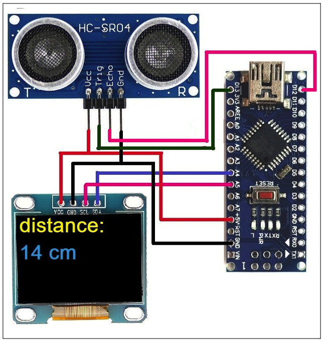
Circuit connections:
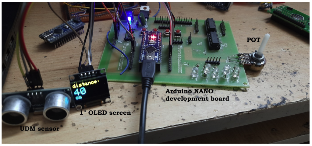
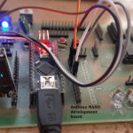
This circuit is built using three components: an Arduino NANO board, an OLED display, and the HC-SR04 sensor.
- The HC-SR04 sensor has four pins: the VCC, GND, Tr, and Echo pins. The VCC and GND pins are connected with Arduino’s +5 V and GND pins. The Tr pin is connected to Arduino’s digital pin 13 and the Echo pin is connected to Arduino’s digital pin 12.
- The OLED has four interfacing pins (as discussed in Part 1): the VCC, GND, SDA, and SCL pins. The VCC and GND pins are connected with Arduino’s +5 V and GND pins, providing the power supply to the display. The SDA and SCL pins are connected with Arduino’s A4 (SDA) and A5 (SCL) pins for data communication.
- Arduino receives its power supply from a computer’s USB port. The onboard voltage regulator chip provides a 5V supply to the HC-SR04 and OLED display.
Circuit operation:
- Arduino continuously sends trigger pulses to the HC-SR04 sensor after each (1) second. As a result, the sensor continuously transmits 40 kHz of ultrasonic pulses.
- Whenever an object is in front of the sensor, these pulses are reflected off the object and detected by the receiver.
- The sensor provides a PWM output to Arduino.
- Arduino measures the width of the pulse and converts it into a distance, displaying the measured distance on the OLED.
The formula Arduino uses:
Distance (in cm) = pulse width (in us)/ 29 / 2
Software program
The Arduino board microcontroller (ATMega328) performs these tasks because of the below program:
1. Provides the trigger pulse input to the HC-SR04 sensor to begin operation.
2. Measures the pulse width output from the HC-SR04 sensor.
3. Converts the pulse width into the distance.
4. Displays the distance on the OLED
This program is written in C/C++ language using Arduino IDE’s software. It’s also compiled and uploaded to Arduino’s microcontroller using the same software.
The program…
This was the final article of the sensor and OLED series. We selected commonly used sensors for these projects, but you can try others — such as the LM35, MQ2 (gas sensor), IR proximity sensor, etc. Essentially, any sensor data can be presented on an OLED display.
Video
You may also like:
Filed Under: Electronic Projects, Sensors
