In Part I of this tutorial, we learned how to present data (or values) using a potentiometer (POT) and an organic light-emitting diode (OLED) display. For this project, the POT was an analog sensor (potentiometers can also be digital), which acts as a resistor to control the flow of an electric current. The OLED technology uses LEDs whereby the light is produced by an organic molecule.
In Part II, we’ll present data using two additional analog sensors:
- Soil-moisture sensor – measures the volumetric water content in soil
- Light-dependent resistor (LDR) – a photoresistor or electronic component that’s sensitive to light
Refer to Part I to review the basics of how to interface an OLED display with Arduino. Here, we’ll begin by discussing how to interface the soil and LDR sensors with Arduino.
The soil-moisture sensor consists of two parts: a sensor probe and a sensor circuit. The sensor probe has two exposed conductors, which act as a variable resistor (much like the POT). Its resistance varies according to the water content in the soil. This resistance is inversely proportional to the soil’s moisture.

A soil-moisture sensor
This means that the greater the water content in the soil, the better the conductivity and less resistance. Inversely, if there is little or no water in the soil, the sensor will have poor conductivity and greater resistance.
This probe is connected to the sensor circuit. The circuit is built using an operational amplifier (op-amp), which works as a comparator. As its name suggests, a comparator is a device that compares two voltages or currents. It then outputs a digital signal that indicates which of the two is larger.
For this project, it provides an analog and digital output. The analog output voltage is set between 0 to 5 V, as the probe resistance varies. The digital output is between 0 and 5 V, as per the threshold voltage set using the POT. A trimmer POT is used here. It is a variable resistor that can adjust or calibrate circuits.
The trimmer(or Trim POT) is used to adjust the sensitivity of the probe. Two LEDs serve as indicators.
1. Power LED – indicates the sensor is active
2. Output LED – turns ON when the digital output (D0) is low (0 V)
Pin names, functions, and connections…

The light-dependent resistor or LDR is also a variable resistor, but it works on the principle of photoconductivity, which means that its resistance depends on the intensity of the light. It’s made up of cadmium sulfide (Cds) material. When light hits this material, the photons lead to an increase in conductivity.
Essentially, the greater the light, the more photons, which increases the conductivity and decreases the resistance. The opposite is also true. If there is little light and few photons, there is little conductivity but more resistance.
This change in resistance is converted into an analog voltage output of between 0 and 5 V using a pull-down resistance.

For this project, we use an LDR module that has the same circuit arrangement with three pins.
Pin names, functions, and connections…

Circuit diagram

Circuit connections
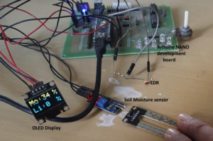
This circuit is built using only four components: an Arduino NANO board, the OLED display, an LDR module, and the soil-moisture sensor.
- The LDR module has three pins: the +V, GND, and signal pins. The +V and GND pins are connected with the Arduino board’s +5 V and GND pins. The signal pin is connected to the analog input pin A1 of the board.
- The soil-moisture sensor module also has the same three pins: the +V, GND, and signal pins. The +V and GND pins are connected with the Arduino board’s +5 V and GND pins. The signal pin is connected to the analog input pin A0 of the board.
- The OLED has four interfacing pins (as discussed in part I of this tutorial): VCC, GND, SDA, and SCL. The VCC and GND pins are connected with Arduino’s +5 V and GND pins, providing the power supply to the display. The SDA and SCL pins are connected with Arduino’s A4 (SDA) and A5 (SCL) pins for data communication.
- Arduino receives its power supply from a computer’s USB port. The onboard voltage regulator chip will provide a 5V supply to both the sensor modules and the OLED display.
Circuit operation
- First, the soil-moisture sensor senses the water content in the soil. The conductivity between its two probes varies based on the moisture level and provides an analog voltage output. If the moisture level is low, the conductivity is also low but the output voltage is high (approx. 5 V) — and vice versa. This means that as the soil moisture level increases the analog output voltage decreases.
- This analog output voltage is read by Arduino, which converts it into a corresponding digital value between 0 and 1023. This digital value is further converted into a percentage (between 0 and 100%).

- As the soil moisture content increases, the analog output voltage decreases and the corresponding percentage value increases — or vice versa.
- The LDR module also gives an analog output voltage as per the intensity of light. As it increases per the LDR, the analog output voltage also increases — or vice versa. If the light decreases, so does the analog output voltage.
- This analog output voltage is also read by Arduino and converted into a corresponding digital value between 0 and 1023. This digital value is further converted into a percentage (between 0 and 100%).

- Arduino converts both sensor values into a percentage range (between 0 and 100%) and displays it on the OLED.
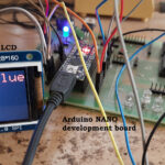
The operating circuit
Software program
The Arduino board microcontroller (ATMega328) performs these tasks when using the below program:
1. Reads the analog voltage output from both sensors
2. Converts the sensor data into a percentage range (between 0 to 100%)
3. Displays the sensors’ data values on the OLED display
This program is written in C/C++ language using Arduino IDE’s software. It’s also compiled and uploaded to Arduino’s microcontroller using the same software.
You may also like:


Filed Under: Electronic Projects, Sensors
