Advantage of 7 segment display–
a. It uses low power for its operation less than 2.5V.
b. Comes in industry standard size.
c. Comes with a industry standard pin out which can be directly referred from datasheet.
d. Seven segment display comes different size, user can use according to their requirement like 7.6mm, 10mm, 14.2mm etc.
e. You can also choose colour of your display. Commonly used- Red, Yellow, and Green.
How to use seven segment displays-
1. Common cathode display – As we know seven segment display are made by combining 8 LED’s. So in this configuration negative lead of all LED’s are connected together and remaining leads used as display. Following circuit shows how to use 7 segment displays in common cathode mode. In this we have connected every segment with the help of resistor to drop excess of voltage. Maximum voltage which it can handle is 2.5V and we are powering it with the supply voltage of 5V. You can use resistor value of 220E to 1K. Depending upon the value of resistor your 7 segment will glow more or less. As you increase the value of resistor brightness of display decreases. Following figure shows the pin configuration of 7 segment display-
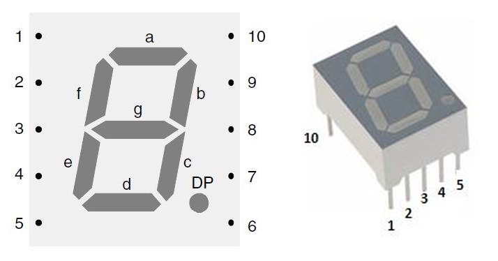
Fig1.
Here letter “a” represents pin 7.
Similarly
Letter “b” represents pin 6.
Letter “c” represents pin 4
Letter “d” represents pin 2
Letter “e” represents pin 1
Letter “f” represents pin 9
Letter “g” represents pin 10
Now suppose you want to display numeric “4” than from figure 1, segment which are used to make “4” are as follows “f”, “g”, “b”, “c” and from above “f” represent pin 9. Similarly “g” represent pin 10, “b” represent pin 6 and “c” represent pin 4. So connect pin 9, 10, 6 and 4 to supply with the help of 220E resistor and ground DP pin 3 or 8 as both are internally connected to each other.Now suppose you want to display alphabet “L” . then segment which you require to glow from figure 1 is “f”, “e”, “d”. Therefore you have to connect pin 9, 1, 2 to supply and ground pin 3. Similarly you can display more alphanumeric on 7 segment display.
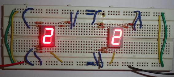
2. Common anode display– In this positive pin of all 8 LED’s connected together and negative leads are used as display pin’s. Always remember to use resistor with individual segment.Now suppose you want to make numeric “2” than segment which we have to use from figure 1 is “a”, “b”, “g”, “e”, “d”. Therefore we have to connect pin 7, 6, 10, 1, 2 to ground and provide power supply to pin 3 that is DP pin.
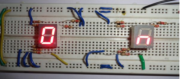
And you want to make letter “n” than connect pin 1, 10, 4 to ground with the help of resistor and provide power supply to pin 3.
Now try to make your own alphanumeric display according to the requirement.
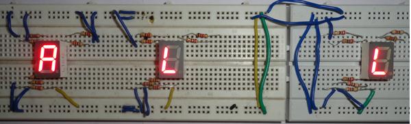
In above picture you can see that we have used both common cathode and anode display to display “A L L”. So now you can also make letters like on, OFF, PAUSE etc for your music system.
Following figure 2 shows the possible combination-
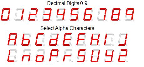
Figure 2
Circuit Diagrams
| How-to-display-numbers-and-alphabet-on-7-segment-display-1 | 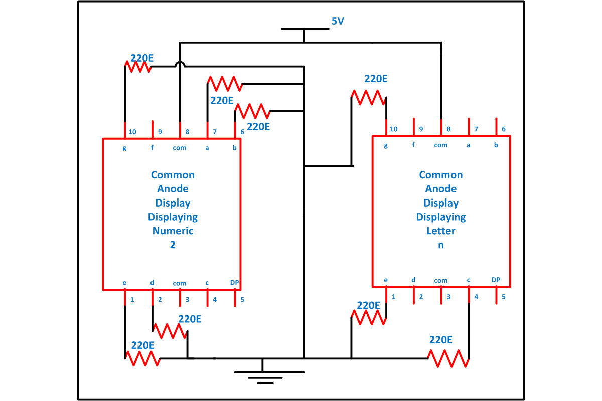 |
| How-to-display-numbers-and-alphabet-on-7-segment-display | 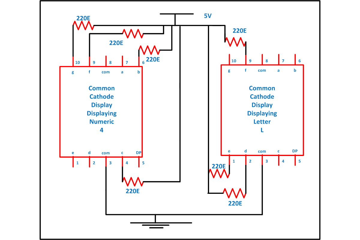 |
Filed Under: Electronic Projects

Questions related to this article?
👉Ask and discuss on Electro-Tech-Online.com and EDAboard.com forums.
Tell Us What You Think!!
You must be logged in to post a comment.