Generating a pure sine wave has its significance especially with devices like microcontrollers which runs on digital voltages. The sine wave is referred to as the basic of all kind of waveform since the combination of sine waves can produce any required wave. In microcontroller systems the analog output like sine wave is generated with the help of digital pulses itself which are generated in such a way that their width are modulated corresponding to the amplitude variations of a sine wave.
The Arduino board is built around an AVR microcontroller and it has all the required circuitary to get the built-in AVR microcontroller running. The Arduino can communicate with the other devices using its digital I/O, serial port, I2C port, SPI port etc. Any AVR microcontroller based board which follows the standard Arduino schematic and is flashed with the Arduino bootloader can be called an Arduino board. The Arduino IDE is so simple to use that anyone who has basic knowledge of c programming can quickly get started with it. The project on how to get started with the Arduino explains the steps required to get start with an Arduino board.
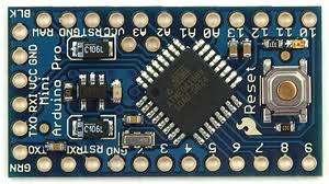
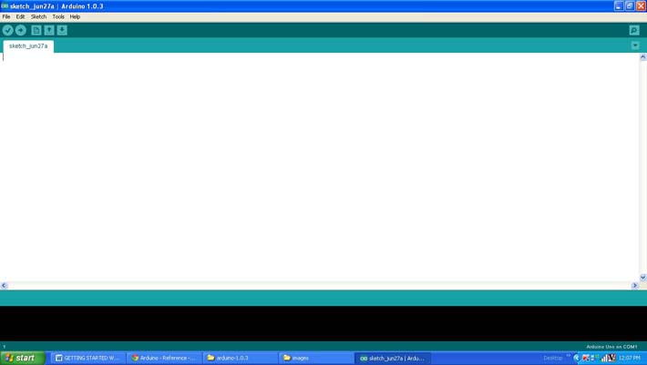
The Arduino board used in this project is the Arduino pro-mini board and the IDE version of the Arduino is 1.0.3 for windows. The image of the Arduino pro-mini board and the Arduino IDE are shown below;

Fig. 2: Typical Arduino Pro-Mini Board

Fig. 3: Arduino IDE Software Window
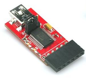
Since the arduino pro-mini board has no circuitary for interfacing it with the serial port or the USB port of the PC, an external USB to TTL converter board is required to connect it with the PC. This hardware helps in programming the Arduino board and also helps in the serial communication with the USB port of the PC.

Fig. 4: External USB to TTL converter board for programming Arduino and serial communication
The Arduino IDE provides several built-in functions which makes the coding very easy. There are functions to access the board itself and there are also functions which help to interface the board with external hardware modules also. The IDE also provides several mathematical and trigonometric functions. Among them there are two functions called sin() and radians() which are make use in this particular project.
sin()
This function returns the sine value of a particular radiance value. The function has one parameter which is the value in the radiance of which the sine value needs to be found. The function returns the sine value which falls in the range of -1 to 1. The parameter is of the type float and the return value is of the type double.
radians()
The function radians() can be used to convert a value in degree to its corresponding value in radians. It has one parameter which is the value in degrees whose radians need to be found. The function returns a float value which is the value in radians corresponding to the input value in degrees.
This project actually generates a square wave whose frequency can be varied with the help of the value read from the analog pin where a potentiometer is connected. The square wave is then used to interrupt the Arduino periodically and inside the ISR the function sin() is used to write a sine value to the analog output pin each time.
The method of generating the square wave and how to vary the frequency is already discussed in a project on how to generate a square wave using Arduino and how to make a simple frequency generator using Arduino. The method of periodically interrupting the Arduino board itself using the square wave generated is also explained in the project on how to interrupt the Arduino board periodically.
In this particular project the ISR is coded in such a way that it writes consecutive sample voltages of a sine wave each and every time the Arduino interrupts itself. The functions sin() and radians() are together used to generate the required sine value which is then written to the analog output pin using the function analogWrite() and hence one can find the sine wave modulated PWM waves at the analog output pin. The modulation frequency depends on how rapidly the Arduino board gets interrupted and which inturn depends on the analog value read from the potentiometer connected at the pin A0 as explained in the project how to make a simple frequency generator using Arduino. The analog value is read from the A0 using the function analogRead() and the details of both the analogRead() and analogWrite() functions are explained in the previous projects on how to use analog input and analog output of Arduino board, how to use Arduino to display sensor values, how to make dynamic sensor display using Arduino, how to save sensor values in the EEPROM of the Arduino.
The pin number 6 which has been configured as the analog output pin is connected to an LED also so that the brightness variation can be observed. When connected to the probes of the CRO and the frequency knob it acts as an envelope demodulator which then displays the demodulated waveform as shown in the following image.

Fig. 5: Demodulated Waveform Of Variable Frequency Sine Wave Using Arduino On Cro
When the coding is finished one can verify and upload the code to the Arduino board as explained in the project how to get started with the Arduino. The square wave can be observed using a CRO which is connected to the pin number 8 and the sine wave can be observed at the pin number 6. One can find that as the potentiometer is varied the frequency of the sine wave is varying.
Project Source Code
###


/*============================ EG LABS ===================================//


 Demonstration on how to generate frequency variable sine wave using Arduino


 * LED anode attached to digital output 6

 * LED cathode attached to ground through a 1K resistor


//============================ EG LABS ===================================*/


int ledPin = 6;                                             // pin number at which the LED is connected

const int analogInPin = A0;                           // pin number at which the potentiometer is connected

float sinVal;                                                   // variable which can hold the sine value

int ledVal;                                                    // variable which can hold the analog value to be written to the analog output pin

int potvalue = 0;                                           // variable which can hold the analog input value


void setup()

{

    pinMode(ledPin, OUTPUT);                                          // making the led pin as output

    attachInterrupt(0, sine_wave, RISING);    // enable the external interrupt 0, with function 'glow' as ISR and
                                                                                         interrupt occurs on rising edge

    tone(8, 1);                                            // generating a tone initially with a frequency of 1 Hz

}


void loop()

{

    potvalue = analogRead(analogInPin);                               // raed the analog value

    tone(8, potvalue * 10);                                           // changing the square wave frequency accordingly

}


//====================== ISR ===========================//

void sine_wave()

{

    static int x = 0;


    x ++;


    //== generatingh the next sine value ==//

    sinVal = (sin(radians(x)));

    ledVal = int(sinVal*255);

    //== generatingh the next sine value ==//


    analogWrite(ledPin, ledVal);                                       // writing sine value to the output pin


    if (x == 180)

      x = 0;

    else;


    noTone(8);

}

//====================== ISR ===========================//

###
Circuit Diagrams
Project Components
Project Video
Filed Under: Arduino
Filed Under: Arduino


Questions related to this article?
👉Ask and discuss on EDAboard.com and Electro-Tech-Online.com forums.
Tell Us What You Think!!
You must be logged in to post a comment.