Engineers Garage

  • Projects and Tutorials
    • Electronic Projects
      • 8051
      • Arduino
      • ARM
      • AVR
      • PIC
      • Raspberry pi
      • STM32
    • Tutorials
    • Circuit Design
    • Project Videos
    • Components
  • Articles
    • Tech Articles
    • Insight
    • Invention Stories
    • How to
    • What Is
  • News
    • Electronic Products News
    • DIY Reviews
    • Guest Post
  • Forums
    • EDABoard.com
    • Electro-Tech-Online
    • EG Forum Archive
  • Digi-Key Store
    • Cables, Wires
    • Connectors, Interconnect
    • Discrete
    • Electromechanical
    • Embedded Computers
    • Enclosures, Hardware, Office
    • Integrated Circuits (ICs)
    • Isolators
    • LED/Optoelectronics
    • Passive
    • Power, Circuit Protection
    • Programmers
    • RF, Wireless
    • Semiconductors
    • Sensors, Transducers
    • Test Products
    • Tools
  • EE Resources
    • DesignFast
    • LEAP Awards
    • Oscilloscope Product Finder
    • White Papers
    • Webinars
  • EE Learning Center
    • Design Guides
      • WiFi & the IOT Design Guide
      • Microcontrollers Design Guide
      • State of the Art Inductors Design Guide
  • Women in Engineering

How to Hack a Wired Mouse

By Ashutosh Bhatt


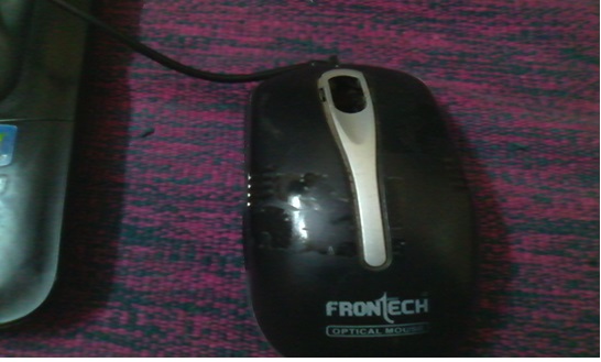
The typical wired mouse.

Uses of a Mouse

After opening the mouse looks like this.

Inside of a Mouse

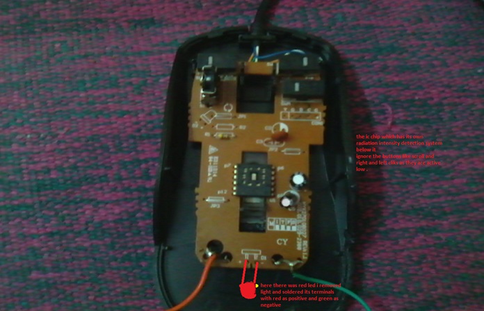
As you see i have soldered the above terminals with the wires which are useful most.

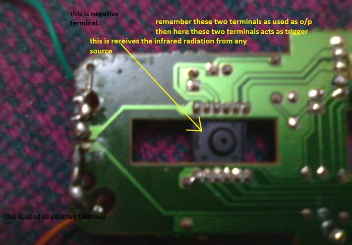
As we turn around we find this

Inside of a Mouse

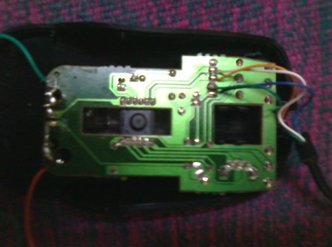
We have an IR detector at the bottom of IC as we see the small hole receives IR rays and measures its intensity. as we see here there are four wires orange ,white ,green ,blue these wires should be kept intact and do not damage the soldering ,take out the black covering carefully,

Then join green as negative of the battery and then blue for the positive of the battery.

Then here we have the main idea is that the chip receives the infrared as when we supply then the output is taken at terminals where i have soldered red and green wires(i.e where there was led),I have shown in the fig above.

9V Battery

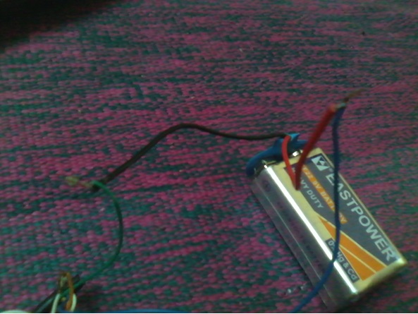
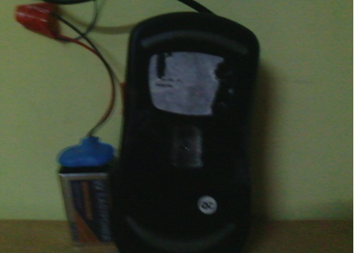
Here is how we connect the power supply. 

Power Supply Connection

Now we fix as it was before, then clearly we have our damn device.

IR LED

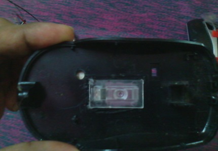
Use this glass piece for better receiving of radiation.

TV Remote

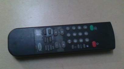
I use the TV remote as the infrared source.

Now it looks ready as follows

Mouse IR LED


Description

As we see the above procedure for developing as wired mouse for a purpose. The positive and the negative terminals are the output terminals. Then we see at the other end of the mouse orange and white are to be joined as we have no use of those, then we see to connect green and blue wire for negative and positive of the battery.

Then here is the concept “when we apply the infrared radiation from the TV remote to the bottom of mouse (i.e. at bottom of the chip)  the output terminals go high about 1.5-2 volts for 1.5 seconds then clearly we find it as a trigger (oneshot)” then we can use this for the various purposes. 

For example

     1. For the counter, i.e. the remote IR LED is fixed in the axis of IC chip then o/p is connected in the place of the clock for serial reload counter which can be got from the engineersgarage.com .this can be used for counting number of people.    

Remote Mouse combination

2. Then we can use this as toy for playing by connecting o/p wires to the

LEDs ,motors etc.

3. These terminals can be connected to the relay then connected to switch through the relay which is so simple there is no need for fig

SwitchBoard

Then we can operate fan, light by TV remote.

4.These wires when connected properly to long electrodes of some small explosive for taking down buildings at construction works, demolition of old crappy buildings(only for educational purpose do not use of illegal purposes which is against the law)

Uses of Mouse


Apply the infrared radiation from the remote to the device.

5. Then clearly we can use this for various purposes. Good luck guys.


Filed Under: How to
Tagged With: mouse
 

Questions related to this article?
👉Ask and discuss on Electro-Tech-Online.com and EDAboard.com forums.


Tell Us What You Think!! Cancel reply

You must be logged in to post a comment.

HAVE A QUESTION?

Have a technical question about an article or other engineering questions? Check out our engineering forums EDABoard.com and Electro-Tech-Online.com where you can get those questions asked and answered by your peers!


Featured Tutorials

  • Introduction to Brain Waves & its Types (Part 1/13)
  • Understanding NeuroSky EEG Chip in Detail (Part 2/13)
  • Performing Experiments with Brainwaves (Part 3/13)
  • Amplification of EEG Signal and Interfacing with Arduino (Part 4/13)
  • Controlling Led brightness using Meditation and attention level (Part 5/13)
  • Control Motor’s Speed using Meditation and Attention Level of Brain (Part 6/13)

Stay Up To Date

Newsletter Signup

Sign up and receive our weekly newsletter for latest Tech articles, Electronics Projects, Tutorial series and other insightful tech content.

EE Training Center Classrooms

EE Classrooms

Recent Articles

  • What is a loop calibrator? 
  • What are the battery-selection criteria for low-power design?
  • Key factors to optimize power consumption in an embedded device
  • EdgeLock A5000 Secure Authenticator
  • How to interface a DS18B20 temperature sensor with MicroPython’s Onewire driver

Most Popular

5G 555 timer circuit 8051 ai Arduino atmega16 automotive avr bluetooth dc motor display Electronic Part Electronic Parts Fujitsu ic infineontechnologies integratedcircuit Intel IoT ir lcd led maximintegratedproducts microchip microchiptechnology Microchip Technology microcontroller microcontrollers mosfet motor powermanagement Raspberry Pi remote renesaselectronics renesaselectronicscorporation Research samsung semiconductor sensor software STMicroelectronics switch Technology vishayintertechnology wireless

RSS EDABOARD.com Discussions

  • 74HC595 creating Fake output
  • What was before microcontrollers ?
  • Check undesired substrate mode...
  • Cap extraction of an IC PAD
  • Active Balun Design

RSS Electro-Tech-Online.com Discussions

  • Question about ultrasonic mist maker
  • Best way to reduce voltage in higher wattage system?
  • Two 300nH inductor in series, can get higher current?
  • Someone please explain how this BMS board is supposed to work?
  • What is "off the shelf values for inductors"?
Engineers Garage
  • Analog IC TIps
  • Connector Tips
  • DesignFast
  • EDABoard Forums
  • EE World Online
  • Electro-Tech-Online Forums
  • Microcontroller Tips
  • Power Electronic Tips
  • Sensor Tips
  • Test and Measurement Tips
  • 5G Technology World
  • About Us
  • Contact Us
  • Advertise

Copyright © 2022 WTWH Media LLC. All Rights Reserved. The material on this site may not be reproduced, distributed, transmitted, cached or otherwise used, except with the prior written permission of WTWH Media
Privacy Policy | Advertising | About Us

Search Engineers Garage

  • Projects and Tutorials
    • Electronic Projects
      • 8051
      • Arduino
      • ARM
      • AVR
      • PIC
      • Raspberry pi
      • STM32
    • Tutorials
    • Circuit Design
    • Project Videos
    • Components
  • Articles
    • Tech Articles
    • Insight
    • Invention Stories
    • How to
    • What Is
  • News
    • Electronic Products News
    • DIY Reviews
    • Guest Post
  • Forums
    • EDABoard.com
    • Electro-Tech-Online
    • EG Forum Archive
  • Digi-Key Store
    • Cables, Wires
    • Connectors, Interconnect
    • Discrete
    • Electromechanical
    • Embedded Computers
    • Enclosures, Hardware, Office
    • Integrated Circuits (ICs)
    • Isolators
    • LED/Optoelectronics
    • Passive
    • Power, Circuit Protection
    • Programmers
    • RF, Wireless
    • Semiconductors
    • Sensors, Transducers
    • Test Products
    • Tools
  • EE Resources
    • DesignFast
    • LEAP Awards
    • Oscilloscope Product Finder
    • White Papers
    • Webinars
  • EE Learning Center
    • Design Guides
      • WiFi & the IOT Design Guide
      • Microcontrollers Design Guide
      • State of the Art Inductors Design Guide
  • Women in Engineering