Engineers Garage

  • Projects and Tutorials
    • Electronic Projects
      • 8051
      • Arduino
      • ARM
      • AVR
      • PIC
      • Raspberry pi
      • STM32
    • Tutorials
    • Circuit Design
    • Project Videos
    • Components
  • Articles
    • Tech Articles
    • Insight
    • Invention Stories
    • How to
    • What Is
  • News
    • Electronic Products News
    • DIY Reviews
    • Guest Post
  • Forums
    • EDABoard.com
    • Electro-Tech-Online
    • EG Forum Archive
  • Digi-Key Store
    • Cables, Wires
    • Connectors, Interconnect
    • Discrete
    • Electromechanical
    • Embedded Computers
    • Enclosures, Hardware, Office
    • Integrated Circuits (ICs)
    • Isolators
    • LED/Optoelectronics
    • Passive
    • Power, Circuit Protection
    • Programmers
    • RF, Wireless
    • Semiconductors
    • Sensors, Transducers
    • Test Products
    • Tools
  • EE Resources
    • DesignFast
    • LEAP Awards
    • Oscilloscope Product Finder
    • White Papers
    • Webinars
  • EE Learning Center
    • Design Guides
      • WiFi & the IOT Design Guide
      • Microcontrollers Design Guide
      • State of the Art Inductors Design Guide
  • Women in Engineering

How to identify and test the seven segment display?

By Anjali Sethiya


 Advantage of seven segment display-

1.  It uses low power for its operation less than 2.5V.

2.Comes in industry standard size.

3.Comes with a industry standard pin out which can be directly referred from datasheet.

4. Seven segment displays comes in different size, so user can use according to their requirement like 7.6mm, 10mm, 14.2mm etc.

 5.You can also choose colour of your display. Commonly used- Red, Yellow, and Green.

Two types of 7 segment display are available in market. And they can be used according to the type of application they are as follows-

1. Common Cathode display– In this type of display, cathode terminal of all LED’s are connect together. If you want to illuminate a segment of common cathode display then provide power supply to that section and ground the common pin (DP). Following figure shows the internal connection of 7 segment common cathode display.
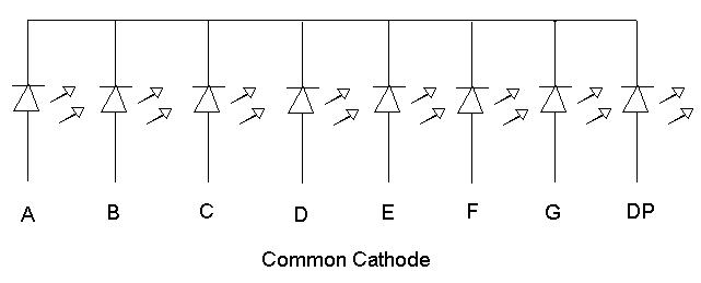
Circuit Diagram of Common Cathode Seven Segment Display (SSD)

Fig. 1: Circuit Diagram of Common Cathode Seven Segment Display (SSD)

2. Common Anode Display– In this type of display, anode terminal of all LED’s are connect together. If you want to illuminate a segment of common anode display then connect that section to ground and provide power supply to common pin (3 and 8 or DP). Following figure shows the internal connection of 7 segment common cathode display.


Circuit Diagram of Common Anode Seven Segment Display (SSD)

Fig. 2: Circuit Diagram of Common Anode Seven Segment Display (SSD)

Always use a resistor while using 7 segment display to illuminate the specify segments, in both 7 segment, common cathode and anode. Because maximum voltage which it can resist is 2.5V therefore excess voltage may harm the individual segment of display. You can use resistor value of 220 ohm or 330 ohm.

How to identify and check the seven segment display-

You have purchase a display from market and you want to confirm whether you have purchase the correct display or your display is working properly or not then you can use the procedure describe below. Suppose you have completely assembled your circuit and through troubleshooting you came to know you have used a incorrect (used common cathode in place of common anode) or faulty display then your time and hard work both will be wasted. So check before you use.

For checking the display you require a simple tool that is your multi-meter. Steps follow while testing seven segment displays–

1. Hold the display in your hand and identify the pin 1.This can be done as shown in figure below.

Image and Pin Diagram of Seven Segment Display (SSD)

Fig. 3: Image and Pin Diagram of Seven Segment Display (SSD)

2. Now take multi-meter (Assumption followed red lead for positive and black lead for negative). Set the multi-meter in continuity range.

3. Check for sound test (touch both the leads together sound will produce). Sometimes it may possible, battery of your multi-meter become weak and we will be not being able to get the display.

4. Put the Black lead of multi-meter on pin 3 or 8 both are common pin as they are internally connected.

5. Now put Red lead of multi-meter on any other pin may be 1, 5.

6. If any of the segment glows then your display is common cathode.

7. If none of the segment glows than interchange the leads of multi-meter.

8. Connect the Red lead of multi-meter on pin 3 or pin 8 as both are common pin and internally connected to each other.

9. Now put the black lead of the multi-meter on other remaining pin. If any of the segment glow than your display is common anode, as in common anode positive pin is common and rest are supplied with negative supply.

10. Check all segments of both common cathode and anode to ensure your display is working properly.

11. If none of the segment glows means your 7 segment is faulty.

 I hope this will save your time and energy for identification and let you know how to test seven segment display.


Filed Under: Tutorials
Tagged With: display, seven segment, seven segment display, testing
 

Questions related to this article?
👉Ask and discuss on Electro-Tech-Online.com and EDAboard.com forums.


Tell Us What You Think!! Cancel reply

You must be logged in to post a comment.

HAVE A QUESTION?

Have a technical question about an article or other engineering questions? Check out our engineering forums EDABoard.com and Electro-Tech-Online.com where you can get those questions asked and answered by your peers!


Featured Tutorials

  • PS2 Keyboard To Store Text In SD Card Using Arduino Circuit Setup On Breadboard
    How To Use PS2 Keyboard To Store Text In SD Card Using Arduino- (Part 42/49)
  • Wireless Path Tracking System Using Mouse, XBee And Arduino Circuit Setup On Breadboard
    How To Make A Wireless Path Tracking System Using Mouse, XBee And Arduino- (Part 43/49)
  • How to Make a Wireless Keyboard Using Xbee with Arduino- (Part 44/49)
  • Making Phone Call From GSM Module Using Arduino Circuit Setup On Breadboard
    How to Make Phonecall From GSM Module Using Arduino- (Part 45/49)
  • How to Make a Call using Keyboard, GSM Module and Arduino
    How To Make A Call Using Keyboard, GSM Module And Arduino- (Part 46/49)
  • Receiving SMS Using GSM Module With Arduino Prototype
    How to Receive SMS Using GSM Module with Arduino- (Part 47/49)

Stay Up To Date

Newsletter Signup

Sign up and receive our weekly newsletter for latest Tech articles, Electronics Projects, Tutorial series and other insightful tech content.

EE Training Center Classrooms

EE Classrooms

Recent Articles

  • Renesas delivers intelligent sensor solutions for IoT applications
  • Microchip Technology releases AVR-IoT Cellular Mini Development Board
  • Qualcomm acquires Cellwize to accelerate 5G adoption and spur infrastructure innovation
  • MediaTek’s chipset offers high-performance option for 5G smartphones
  • Nexperia’s new level translators support legacy and future mobile SIM cards

Most Popular

5G 555 timer circuit 8051 ai Arduino atmega16 automotive avr bluetooth dc motor display Electronic Part Electronic Parts Fujitsu ic infineontechnologies integratedcircuit Intel IoT ir lcd led maximintegratedproducts microchip microchiptechnology Microchip Technology microcontroller microcontrollers mosfet motor powermanagement Raspberry Pi remote renesaselectronics renesaselectronicscorporation Research samsung semiconductor sensor software STMicroelectronics switch Technology vishayintertechnology wireless

RSS EDABOARD.com Discussions

  • DC Motor Speed Control
  • D Flip Flop frequency divider
  • FPGA LVDS with separate clock
  • How do you find the angle made by two isosceles triangles in a kite?
  • Limits of duty cycle for ICM7555 IC?

RSS Electro-Tech-Online.com Discussions

  • RF modules which can handle high number of bytes per second
  • we are facing an issue with one-wire communication by using DS2485
  • Are Cross-wind compensation and Road crown compensation functions inputs to LKA function?
  • Component identification.
  • Flickering (candle) LED to trigger 555
Engineers Garage
  • Analog IC TIps
  • Connector Tips
  • DesignFast
  • EDABoard Forums
  • EE World Online
  • Electro-Tech-Online Forums
  • Microcontroller Tips
  • Power Electronic Tips
  • Sensor Tips
  • Test and Measurement Tips
  • 5G Technology World
  • About Us
  • Contact Us
  • Advertise

Copyright © 2022 WTWH Media LLC. All Rights Reserved. The material on this site may not be reproduced, distributed, transmitted, cached or otherwise used, except with the prior written permission of WTWH Media
Privacy Policy | Advertising | About Us

Search Engineers Garage

  • Projects and Tutorials
    • Electronic Projects
      • 8051
      • Arduino
      • ARM
      • AVR
      • PIC
      • Raspberry pi
      • STM32
    • Tutorials
    • Circuit Design
    • Project Videos
    • Components
  • Articles
    • Tech Articles
    • Insight
    • Invention Stories
    • How to
    • What Is
  • News
    • Electronic Products News
    • DIY Reviews
    • Guest Post
  • Forums
    • EDABoard.com
    • Electro-Tech-Online
    • EG Forum Archive
  • Digi-Key Store
    • Cables, Wires
    • Connectors, Interconnect
    • Discrete
    • Electromechanical
    • Embedded Computers
    • Enclosures, Hardware, Office
    • Integrated Circuits (ICs)
    • Isolators
    • LED/Optoelectronics
    • Passive
    • Power, Circuit Protection
    • Programmers
    • RF, Wireless
    • Semiconductors
    • Sensors, Transducers
    • Test Products
    • Tools
  • EE Resources
    • DesignFast
    • LEAP Awards
    • Oscilloscope Product Finder
    • White Papers
    • Webinars
  • EE Learning Center
    • Design Guides
      • WiFi & the IOT Design Guide
      • Microcontrollers Design Guide
      • State of the Art Inductors Design Guide
  • Women in Engineering