How to increase transmission range by increasing height of Tx antenna?
Background:
There are two methods to increase transmission range of 434 MHz RF Tx module.
1. Increase applied input power – transmitted power
2. Attach an antenna to Tx module
In previous article, I have explained first method. Please refer previous article of this series. In this session we will see another method. That means we will attach an antenna to Tx and Rx module. Antenna is a special type of transducer, which can convert alternating current in to radio frequency fields and vice versa. Transmitting antenna generates RF fields, and receiving antenna converts RF fields in to alternating current.
In this project I will attach antenna to transmitter and receiver and try to increase the range.
In this project we shall keep other factors constant like applied input power, and connect suitable length of antenna and we will achieve long range.
Description:
In this project antenna plays a vital role. Any simple conductor can act as an antenna. But when we have to connect an antenna, we have to do some calculations based on radio technology theory. Any length of conductor can act as an antenna but because of several factors we have to calculate antenna size, just like antenna gain etc.
The antenna calculations are mainly for height of an antenna. To calculate antenna height, wavelength, velocity and frequency are the main factors.
Based on frequency and wavelength, the antenna size varies. For basic 434 MHz antenna calculations are as below.
Antenna size calculations:
The frequency of the RF carrier is = 434 Mhz.
Frequency = cycles/sec
= 434 M/sec
Time period = 1/ frequency
= 1/434×106
= 2.3 nsec
Speed of light (c) = 3×10 m/sec
Then,
Wavelength = speed / frequency.
= speed × time period
= 2.3 nsec × 3×10⁸ m/sec
= 0.69 m
As per antenna theory antenna size should be half or quarter size of the wavelength.
So
Quarter wavelength = 0.69 m/4
= 17.25cm.
Required components and other equipments:
Sr. no. Name of component Required qut
1 RF Tx module(434Mhz) 1
2 RF Rx module(434Mhz) 1
3 HT12E 1
4 HT12D 1
5 LED 5
6 Resistor – 1KΩ (Quarter watt) 8
7 Resistor – 1MΩ (Quarter watt) 1
8 Resistor – 50KΩ (Quarter watt) 1
9 Pushbutton 4
11 Battery – 9V 2
15 Bread board 2
18 connecting wires —
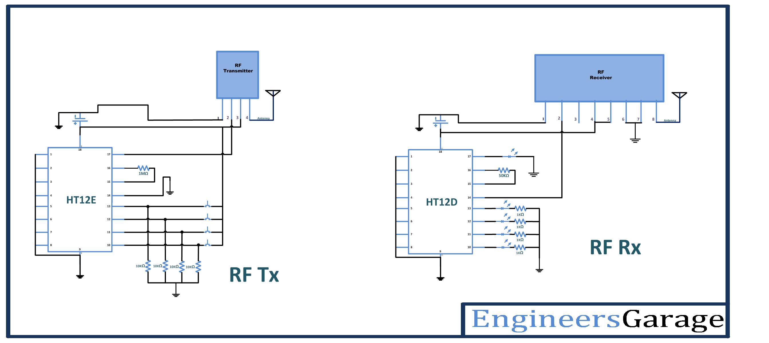
Circuit diagram:
Description:
Procedure:
Transmitter section:
Step1: connect the four push buttons to the data input pins (10, 11, 12, 13) of HT12E, with pull down resistors of 1 K.
Step2: connect 1MΩ resistor between 15 and 16 pins of HT12E.
Step3: connect 17 pin to the 2nd pin of RF transmitter, and 14 pin connect to the ground.
Step4: 1-8 pins of HT12E are address pins, connect all to the ground. And connect pin 18 to Vcc and pin 9 to ground.
Step5: Connect RF Tx module’s pin 1 to the ground, pin 3 to the Vcc and pin 4 to the antenna.
Step6: calculate the antenna size using antenna theory, and connect at 4th pin of Tx module
Receiver section:
Step1: connect four LED’s to the output pins (10, 11, 12, 13) of HT12D, with pull down resistors.
Step2: connect 50KΩ resistor between 15 and 16 pins of HT12D.
Step3: connect pin 14 of HT12D to the 2nd pin of RF transmitter. Connect pin 17 to the LED indicator (it will glow when signal is received)
Step4: pins 1-8 of HT12D are address pins, connect all to the ground. Connect pin 18 to Vcc and pin 9 to ground.
Step5: Connect RF Rx module’s 1, 6, 7 pins to the ground, pins 4 & 5 to the Vcc and pin 8 to the antenna.
Step6: calculate the antenna size using antenna theory, and connect at 8th pin of Rx module
Now let us look at the operation of circuit
Working:
1. When any switch is pressed at encoder input pin, the encoder generates a data sequence at 14th pin that is fed to the 2nd pin of Tx module. Tx module transmits signal as ASK modulated signal with data in amplitude variations. At receiver side, received signal is given to the pin 14 of decoder chip, from pin 2 of Rx module. As a output, respective Led will glow at decoder output pins
2. Note down the readings for distance as a transmitted range in line of sight and non line of sight with 9 V battery without connecting antenna on either side
3. Now connect antenna (size should be as per calculations), and test line of site and non line of site wireless communication between Tx and Rx. Note down the readings of the distance, and compare the present readings with previous readings.
Without antenna With antenna
Range -> 70m 156m
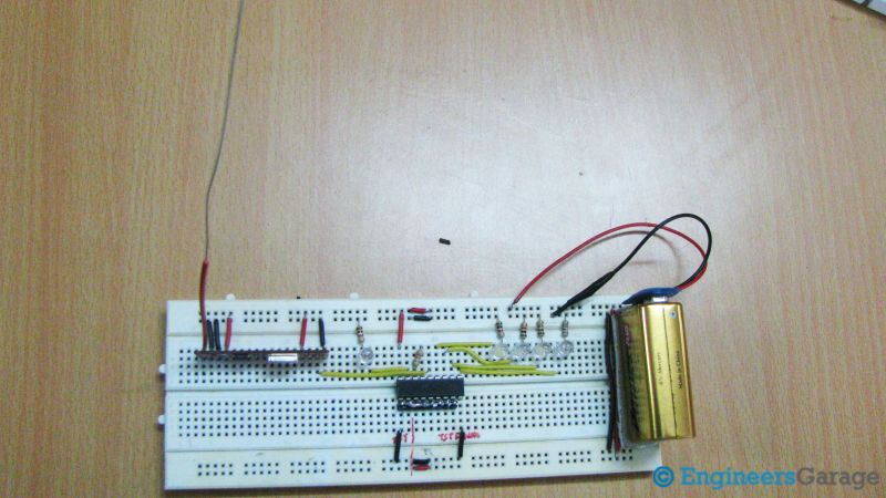
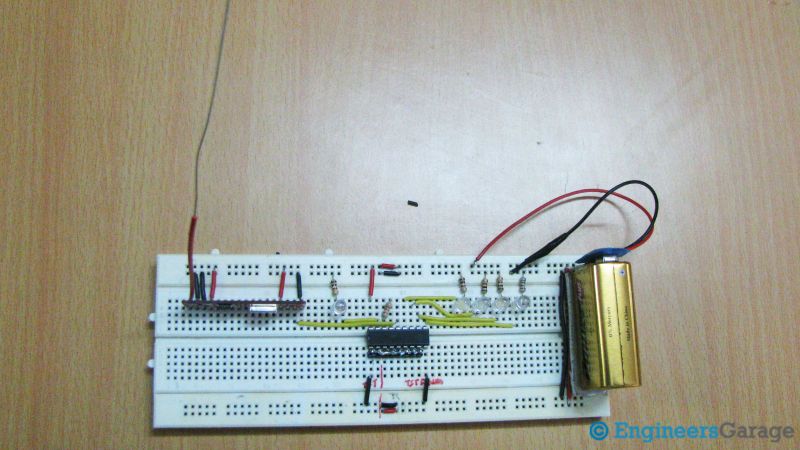
pictures:


Precautions:
1. Address lines should be same at both transmitter and receiver side.
2. At transmitter 14th pin of HT12E should be connect to ground or connect a switch between ground and the 14th pin to reset the encoder.
3. At transmitter side resistor between 15 and 16 pins of HT12E should be between 750MΩ to 1MΩ and at receiver side resistor between 15 and 16 pins of HT12D should be between 30KΩ to 50KΩ.
4. Incase if you want to use any other battery please check the data sheets of HT12E/HT12D before.

You may also like:


Project Source Code
Project Source Code
###

//Program to
Circuit Diagrams
Filed Under: Circuit Design, Electronic Projects

Questions related to this article?
👉Ask and discuss on EDAboard.com and Electro-Tech-Online.com forums.
Tell Us What You Think!!
You must be logged in to post a comment.