Engineers Garage

  • Electronic Projects & Tutorials
    • Electronic Projects
      • Arduino Projects
      • AVR
      • Raspberry pi
      • ESP8266
      • BeagleBone
      • 8051 Microcontroller
      • ARM
      • PIC Microcontroller
      • STM32
    • Tutorials
      • Audio Electronics
      • Battery Management
      • Brainwave
      • Electric Vehicles
      • EMI/EMC/RFI
      • Hardware Filters
      • IoT tutorials
      • Power Tutorials
      • Python
      • Sensors
      • USB
      • VHDL
    • Circuit Design
    • Project Videos
    • Components
  • Articles
    • Tech Articles
    • Insight
    • Invention Stories
    • How to
    • What Is
  • News
    • Electronic Product News
    • Business News
    • Company/Start-up News
    • DIY Reviews
    • Guest Post
  • Forums
    • EDABoard.com
    • Electro-Tech-Online
    • EG Forum Archive
  • DigiKey Store
    • Cables, Wires
    • Connectors, Interconnect
    • Discrete
    • Electromechanical
    • Embedded Computers
    • Enclosures, Hardware, Office
    • Integrated Circuits (ICs)
    • Isolators
    • LED/Optoelectronics
    • Passive
    • Power, Circuit Protection
    • Programmers
    • RF, Wireless
    • Semiconductors
    • Sensors, Transducers
    • Test Products
    • Tools
  • Learn
    • eBooks/Tech Tips
    • Design Guides
    • Learning Center
    • Tech Toolboxes
    • Webinars & Digital Events
  • Resources
    • Digital Issues
    • EE Training Days
    • LEAP Awards
    • Podcasts
    • Webinars / Digital Events
    • White Papers
    • Engineering Diversity & Inclusion
    • DesignFast
  • Guest Post Guidelines
  • Advertise
  • Subscribe

How to interface 16×2 LCD in 4-bit mode with PIC Microcontroller (PIC18F4550)- (Part 7/25)

By Amit Joshi May 19, 2011

The 16x2 character LCD can work in two modes, namely, 8-bit and 4-bit. These modes basically correspond to the number of data pins used in interfacing LCD. 8-bit mode uses all the data lines and has been explained in LCD interfacing with PIC18F4550. In 4-bit mode, only four data pins of LCD are connected to the controller. This mode, thus, saves four pins of the controller unlike 8-bit mode. The configuration and display method of LCD in 4-bit mode has been explained here.


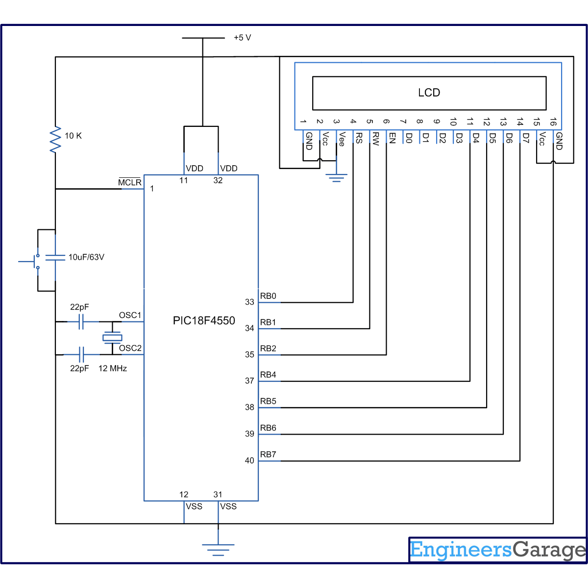
The 8-bit mode of LCD interfacing with PIC has been explained earlier. In the 4-bit mode the (8-bit) data/command is sent in nibble (four bits) format to LCD. The higher nibble is sent first followed by the lower nibble. In 4-bit mode only four data pins (D4-D7) of LCD are connected to the controller. The control pins (RS, RW and EN) are connected the same way as in 8-bit mode. The connections of LCD with PIC18F4550 are shown in the adjoining circuit diagram. Please note that here only PortB is used to connect data lines as well as control lines unlike in 8-bit mode. Refer LCD interfacing with PIC in 8-bit mode.

LCD is configured for 4-bit mode by sending appropriate instruction known as Function Set. The Function Set is hexadecimal instruction for LCD MPU unit which selects the working modes of LCD. The Function Set is given below along with its description. 
Instruction
RS
RW
D7
D6
D5
D4
D3
D2
D1
D0
Function Set
0
0
0
0
1
DL
N
F
–
–
 
Description: 
DL       –           Data Length               
N         –           No. of Lines               
F          –           Font                           
 
 Value
 DL
 N
F
1
8 bit
2 lines
5×10 dots
0
4 bit
1 line
5×7 dots
 
Fig. 2: Bit Values to Configure LCD in 4-bit mode with PIC18F4550 
 
According to the table, the value of Function Set for 4–bit mode will be [ 0010 0000 ] 0x20. The value of Function Set for the LCD configuration : 2 line (N=1), 5×7 dots (F=0) and 4-bit (DL=0) mode will be [ 0010 1000 ] 0x28.
 
It is important to note that when the power supply is given to LCD, it remains in 8-bit mode. In this state if 0x20 is sent, lower nibble will not be received by LCD because only four data lines (D4-D7) are connected, so 0x02 is sent instead of 0x20.
 
For more details on nibble arrangement and bit shifting, refer LCD 4-bit mode with AVR.


Project Source Code

###

// Program to interface 16x2 LCD with PIC18F4550 Microcontroller using 4-bit mode

// Configuration bits
/* _CPUDIV_OSC1_PLL2_1L,  // Divide clock by 2
   _FOSC_HS_1H,           // Select High Speed (HS) oscillator
   _WDT_OFF_2H,           // Watchdog Timer off
   MCLRE_ON_3H            // Master Clear on
*/

//LCD Control pins
#define rs LATA.F0
#define rw LATA.F1
#define en LATA.F2

//LCD Data pins
#define lcdport LATB

void lcd_ini();
void dis_cmd(unsigned char);
void dis_data(unsigned char);
void lcdcmd(unsigned char);
void lcddata(unsigned char);

void main(void)
{
	unsigned char data0[]="EngineersGarage";
	unsigned int i=0;
	TRISB=0;			// Configure Port B as output port
	LATB=0;
	lcd_ini();			// LCD initialization
	while(data0[i]!='')
	{
		dis_data(data0[i]);
		Delay_ms(200);
		i++;
	}
}
void lcd_ini()	                    
{
	dis_cmd(0x02);		// To initialize LCD in 4-bit mode.
	dis_cmd(0x28);		// To initialize LCD in 2 lines, 5x7 dots and 4bit mode.
	dis_cmd(0x0C);
	dis_cmd(0x06);
	dis_cmd(0x80);
}

void dis_cmd(unsigned char cmd_value)
{
	unsigned char cmd_value1;
	cmd_value1 = (cmd_value & 0xF0);	// Mask lower nibble because RB4-RB7 pins are being used
	lcdcmd(cmd_value1);			// Send to LCD
	cmd_value1 = ((cmd_value<<4) & 0xF0);	// Shift 4-bit and mask
	lcdcmd(cmd_value1);			// Send to LCD
}


void dis_data(unsigned char data_value)
{
	unsigned char data_value1;
	data_value1=(data_value&0xF0);
	lcddata(data_value1);
	data_value1=((data_value<<4)&0xF0);
	lcddata(data_value1);
}

void lcdcmd(unsigned char cmdout)
{
	lcdport=cmdout;		//Send command to lcdport=PORTB
	rs=0;						
	rw=0;
	en=1;
	Delay_ms(10);
	en=0;
}

void lcddata(unsigned char dataout)
{
	lcdport=dataout;	//Send data to lcdport=PORTB
	rs=1;
	rw=0;
	en=1;
	Delay_ms(10);
	en=0;
}

###


Circuit Diagrams

Circuit-Diagram-of-How-to-interface-16×2-LCD-in-4-bit-mode-with-PIC-Microcontroller-PIC18F4550

Project Components

  • LCD
  • PIC18F4550

Project Video


Filed Under: PIC Microcontroller
Tagged With: 4bit, display, lcd, microcontroller, pic18f4550
 

Next Article

← Previous Article
Next Article →

Questions related to this article?
👉Ask and discuss on Electro-Tech-Online.com and EDAboard.com forums.


Tell Us What You Think!! Cancel reply

You must be logged in to post a comment.

EE TECH TOOLBOX

“ee
Tech Toolbox: Internet of Things
Explore practical strategies for minimizing attack surfaces, managing memory efficiently, and securing firmware. Download now to ensure your IoT implementations remain secure, efficient, and future-ready.

EE Learning Center

EE Learning Center
“engineers
EXPAND YOUR KNOWLEDGE AND STAY CONNECTED
Get the latest info on technologies, tools and strategies for EE professionals.

HAVE A QUESTION?

Have a technical question about an article or other engineering questions? Check out our engineering forums EDABoard.com and Electro-Tech-Online.com where you can get those questions asked and answered by your peers!


RSS EDABOARD.com Discussions

  • Reducing "shoot-through" in offline Full Bridge SMPS?
  • What is the purpose of using a VCVS?
  • Checking line impedance
  • Why do I hear whistling sounds in my vents?
  • Mains inverter with switching node going out on the mains cable!?

RSS Electro-Tech-Online.com Discussions

  • Why can't I breadboard this oscillator?
  • Failure of polypropylene motor-run capacitors
  • a point I can't understand about the sinc expression
  • Quick advice on remote car starter?
  • Wideband matching an electrically short bowtie antenna; 50 ohm, 434 MHz

Featured – RPi Python Programming (27 Part)

  • RPi Python Programming 21: The SIM900A AT commands
  • RPi Python Programming 22: Calls & SMS using a SIM900A GSM-GPRS modem
  • RPi Python Programming 23: Interfacing a NEO-6MV2 GPS module with Raspberry Pi
  • RPi Python Programming 24: I2C explained
  • RPi Python Programming 25 – Synchronous serial communication in Raspberry Pi using I2C protocol
  • RPi Python Programming 26 – Interfacing ADXL345 accelerometer sensor with Raspberry Pi

Recent Articles

  • AC-DC power supply extends voltage range to 800 V DC
  • Infineon’s inductive sensor integrates coil system driver, signal conditioning circuits and DSP
  • Arm Cortex-M23 MCU delivers 87.5 µA/MHz active mode
  • STMicroelectronics releases automotive amplifiers with in-play open-load detection
  • Convection-cooled power controller integrates EtherCat connectivity

EE ENGINEERING TRAINING DAYS

engineering

Submit a Guest Post

submit a guest post
Engineers Garage
  • Analog IC TIps
  • Connector Tips
  • Battery Power Tips
  • DesignFast
  • EDABoard Forums
  • EE World Online
  • Electro-Tech-Online Forums
  • EV Engineering
  • Microcontroller Tips
  • Power Electronic Tips
  • Sensor Tips
  • Test and Measurement Tips
  • 5G Technology World
  • Subscribe to our newsletter
  • About Us
  • Contact Us
  • Advertise

Copyright © 2025 WTWH Media LLC. All Rights Reserved. The material on this site may not be reproduced, distributed, transmitted, cached or otherwise used, except with the prior written permission of WTWH Media
Privacy Policy

Search Engineers Garage

  • Electronic Projects & Tutorials
    • Electronic Projects
      • Arduino Projects
      • AVR
      • Raspberry pi
      • ESP8266
      • BeagleBone
      • 8051 Microcontroller
      • ARM
      • PIC Microcontroller
      • STM32
    • Tutorials
      • Audio Electronics
      • Battery Management
      • Brainwave
      • Electric Vehicles
      • EMI/EMC/RFI
      • Hardware Filters
      • IoT tutorials
      • Power Tutorials
      • Python
      • Sensors
      • USB
      • VHDL
    • Circuit Design
    • Project Videos
    • Components
  • Articles
    • Tech Articles
    • Insight
    • Invention Stories
    • How to
    • What Is
  • News
    • Electronic Product News
    • Business News
    • Company/Start-up News
    • DIY Reviews
    • Guest Post
  • Forums
    • EDABoard.com
    • Electro-Tech-Online
    • EG Forum Archive
  • DigiKey Store
    • Cables, Wires
    • Connectors, Interconnect
    • Discrete
    • Electromechanical
    • Embedded Computers
    • Enclosures, Hardware, Office
    • Integrated Circuits (ICs)
    • Isolators
    • LED/Optoelectronics
    • Passive
    • Power, Circuit Protection
    • Programmers
    • RF, Wireless
    • Semiconductors
    • Sensors, Transducers
    • Test Products
    • Tools
  • Learn
    • eBooks/Tech Tips
    • Design Guides
    • Learning Center
    • Tech Toolboxes
    • Webinars & Digital Events
  • Resources
    • Digital Issues
    • EE Training Days
    • LEAP Awards
    • Podcasts
    • Webinars / Digital Events
    • White Papers
    • Engineering Diversity & Inclusion
    • DesignFast
  • Guest Post Guidelines
  • Advertise
  • Subscribe