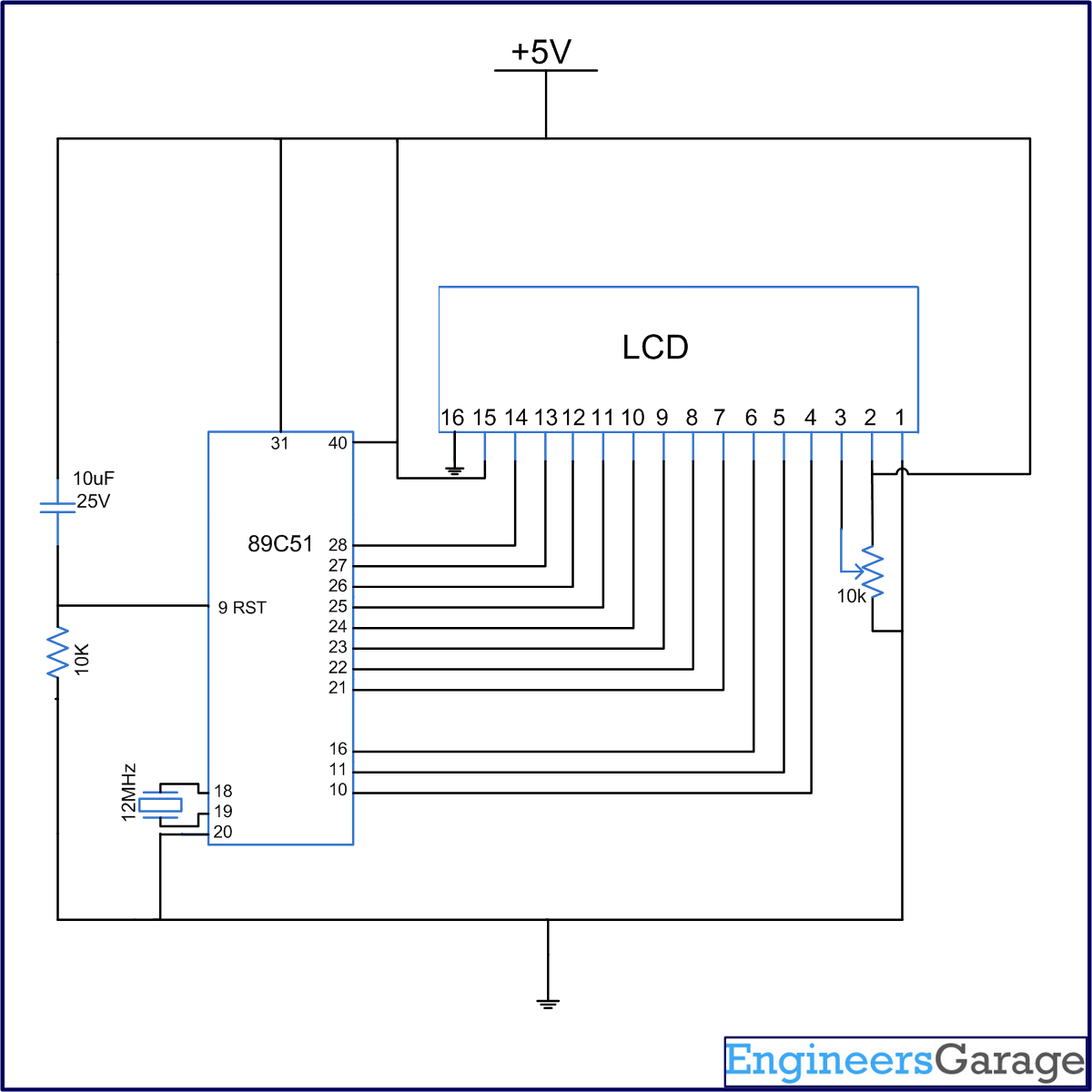
It is very important to keep a track of the working of almost all the automated and semi-automated devices, be it a washing machine, an autonomous robot or anything else. This is achieved by displaying their status on a small display module. LCD (Liquid Crystal Display) screen is such a display module and a 16x2 LCD module is very commonly used. These modules are replacing seven segments and other multi segment LEDs for these purposes. The reasons being: LCDs are economical, easily programmable, have no limitation of displaying special & even custom characters (unlike in seven segments), animations and so on. LCD can be easily interfaced with a microcontroller to display a message or status of a device. This topic explains the basics of a 16x2 LCD and how it can be interfaced with AT89C51 to display a character.
A 16x2 LCD means it can display 16 characters per line and there are 2 such lines. In this LCD each character is displayed in 5×7 pixel matrix. This LCD has two registers.
1. Command/Instruction Register – stores the command instructions given to the LCD. A command is an instruction given to LCD to do a predefined task like initializing, clearing the screen, setting the cursor position, controlling display etc.
2. Data Register – stores the data to be displayed on the LCD. The data is the ASCII value of the character to be displayed on the LCD.
|
Hex Code
|
Command to LCD Instruction Register
|
|
1
|
Clear screen display
|
|
2
|
Return home
|
|
4
|
Decrement cursor
|
|
6
|
Increment cursor
|
|
E
|
Display ON, Cursor ON
|
|
80
|
Force the cursor to the beginning of the 1st line
|
|
C0
|
Force cursor to the beginning of the 2nd line
|
|
38
|
Use 2 lines and 5×7 matrix
|
|
Pin
|
Symbol
|
Description
|
|
|
1
|
VSS
|
Ground
|
0 V
|
|
2
|
VCC
|
Main power supply
|
+5 V
|
|
3
|
VEE
|
Power supply to control contrast
|
Contrast adjustment by providing a variable resistor through VCC
|
|
4
|
RS
|
Register Select
|
RS=0 to select Command Register
RS=1 to select Data Register
|
|
5
|
R/W
|
Read/write
|
R/W=0 to write to the register
R/W=1 to read from the register
|
|
6
|
EN
|
Enable
|
A high to low pulse (minimum 450ns wide) is given when data is sent to data pins
|
|
7
|
DB0
|
To display letters or numbers, their ASCII codes are sent to data pins (with RS=1). Also instruction command codes are sent to these pins.
|
|
|
8
|
DB1
|
|
|
|
9
|
DB2
|
|
|
|
10
|
DB3
|
8-bit data pins
|
|
|
11
|
DB4
|
||
|
12
|
DB5
|
|
|
|
13
|
DB6
|
|
|
|
14
|
DB7
|
|
|
|
15
|
Led+
|
Backlight VCC
|
+5 V
|
|
16
|
Led-
|
Backlight Ground
|
0 V
|
Project Source Code
###

//Program to test LCD. Display single character "A"

#include<reg51.h>
#define cmdport P3
#define dataport P2
#define q 100
sbit rs = cmdport^0;  //register select pin
sbit rw = cmdport^1;  // read write pin
sbit e = cmdport^6;  //enable pin

void delay(unsigned int msec)  // Function to provide time delay in msec.
{
int i,j ;
for(i=0;i<msec;i++)
for(j=0;j<1275;j++);
}

void lcdcmd(unsigned char item)  //Function to send command to LCD
{
dataport = item;
rs= 0;
rw=0;
e=1;
delay(1);
e=0;
}

void lcddata(unsigned char item)  //Function to send data to LCD
{
dataport = item;
rs= 1;
rw=0;
e=1;
delay(1);
e=0;
}

void main()
{
lcdcmd(0x38);  // for using 8-bit 2 row mode of LCD
delay(100);
lcdcmd(0x0E);  // turn display ON for cursor blinking
delay(100);
lcdcmd(0x01);  //clear screen
delay(100);
lcdcmd(0x06);  //display ON
delay(100);
lcdcmd(0x86);  // bring cursor to position 6 of line 1
delay(100);
lcddata('A');
}
###
Circuit Diagrams
Project Components
Project Video
Filed Under: 8051 Microcontroller.
Filed Under: 8051 Microcontroller.


Questions related to this article?
👉Ask and discuss on EDAboard.com and Electro-Tech-Online.com forums.
Tell Us What You Think!!
You must be logged in to post a comment.