Engineers Garage

  • Projects and Tutorials
    • Electronic Projects
      • 8051
      • Arduino
      • ARM
      • AVR
      • PIC
      • Raspberry pi
      • STM32
    • Tutorials
    • Circuit Design
    • Project Videos
    • Components
  • Articles
    • Tech Articles
    • Insight
    • Invention Stories
    • How to
    • What Is
  • News
    • Electronic Products News
    • DIY Reviews
    • Guest Post
  • Forums
    • EDABoard.com
    • Electro-Tech-Online
    • EG Forum Archive
  • Digi-Key Store
    • Cables, Wires
    • Connectors, Interconnect
    • Discrete
    • Electromechanical
    • Embedded Computers
    • Enclosures, Hardware, Office
    • Integrated Circuits (ICs)
    • Isolators
    • LED/Optoelectronics
    • Passive
    • Power, Circuit Protection
    • Programmers
    • RF, Wireless
    • Semiconductors
    • Sensors, Transducers
    • Test Products
    • Tools
  • EE Resources
    • DesignFast
    • LEAP Awards
    • Oscilloscope Product Finder
    • White Papers
    • Webinars
  • EE Learning Center
    • Design Guides
      • WiFi & the IOT Design Guide
      • Microcontrollers Design Guide
      • State of the Art Inductors Design Guide
  • Women in Engineering

How to Interface 4×4 Matrix Keypad with LPC2148- (Part 6/9)

By Dishant Shah

Switch is the most widely used input device. When a switch is pressed either low or high signal is given to controller depending upon the circuit designing. This approach requires one pin for a single switch. With increasing requirement of input devices, more numbers of controller pins are required which may not be available all the time. For example, to enter value from 0 to 15, we need 16 pins of controller to be interfaced with switches. To reduce number of required pins, we can arrange keys in matrix form.

Matrix keypad is one of the widely used input devices. Some of the application includes Mobile keypad, Telephone dial pad, calculator, ATM etc. Keypad provides an easy way to allow user to provide input to any system. In this article, we will explain how to interface 4x4 matrix keypad with LPC2148. The pressed key will be displayed on LCD.

Here is a simple comparison of two different approaches.

[[wysiwyg_imageupload:11365:]]

Fig. 1: Comparison between switches and Matrix Keypad 

If we have to identify X=a*b characters, we need only a+b pins from controller as explained in table


In matrix keypad, keys are connected in rows and columns. When any switch is pressed, rows and columns come into contact which is detected by controller to identify which key has been pressed. Let’s see how keypad works. 

Keypad in general looks like this.

Diagram of Matrix Keypad

Fig. 3: Diagram Of Matrix Keypad

For identify the pressed key, we have to follow given procedure.

Flow Chart of Detecting Pressed Key

Fig. 4: Flow Chart Of Detecting Pressed Key

Step-1: Set output port to logic 0 and input port to logic 1.

If all rows are set to logic 1 and no key is pressed, reading input port will result all input pins set at logic 1 as there is no path available for current to flow between Vcc and Ground. It is a function of micro-controller to read input port continuously to identify whether the key has been pressed or not.

Step-2:  Whenever any key is pressed, one of the input pin will be grounded by pressed key. By reading input pins, we can identify the column in which key has been pressed by following table.

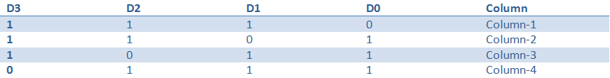
So now we have identify that in which column the key has been pressed by user. Now we have to identify the row in which key has been pressed.

Step-3: Ground first row and set rest of the rows. Read input port. If all are 1s, no switch in that row is pressed. Now ground second row and set all others rows at logic 1 and see whether any key has been pressed in that row or not. Continue same process until you find out in which row, key is pressed.

Once we know column and row in which key has been pressed, we can identify the pressed key easily.

Step-4: Ground all rows and read columns. If any of the columns has 0, keep doing this process unless all columns are 1.

Step-5: Once we have identified the pressed key, we can display it on LCD, Serial Port etc. as per the requirement.

Project Source Code

###

//Program to interface 16x2 LCD with LPC 2148
// Pressed key has been displayed on LCD using this functions

#include <LPC21xx.h>

#include "lcd4bit.h"
 void write_command(int cmd)
 {

                IO1CLR  |= 0x00f00000;                 /* Clear D4-D7  */
                IO1CLR  |= 0x00040000;                 /* Read/Write = 0              */
                IO1CLR  |= 0X00020000;                    /* Register Select = 0,Command */
                IO1SET  |= 0x00f00000 & cmd;                        /* Set D4-D7    */
IO1SET  |= 0X00080000;                 /* Enable = 1                                   */ 
Delay(30000);
IO1CLR  |= 0x00080000;                 /* set E to low   */
  }
void write_data(int dat)
{
IO1CLR  |= 0x00f00000;                 /* Clear D4-D7  */
IO1CLR  |= 0x00040000;                 /* Read/Write = 0     */
IO1SET  |= 0X00020000;           /* Register Select = 1,Data */
IO1SET  |= 0x00f00000 & dat;                                      /* Set D4-D7    */
IO1SET  |= 0X00080000;         /* Enable = 1      */
Delay(30000);                      //delay ~2ms
IO1CLR  |= 0x00080000;                  /* Set E to low            */
}
void lcd_data(char dat)
{
                 write_data(dat << 16);
 write_data(dat << 20);
}
void lcd_command(char cmd)
{
  write_command(cmd << 16);
  write_command(cmd << 20);
}
void printlcd(char *CPtr)
{
  while(*CPtr != '')
{
                                lcd_data(*CPtr);
CPtr++;
                                Delay(20000);
                }
}
void init_lcd(void)
{                                                                                                                                                              
                IO1DIR |= 0x00FE0000;   
Delay(200000) ;
write_command(0x28 << 16);
Delay(100000);
lcd_command(0x01);                              /* clear display */
lcd_command(0x06);                              /* auto address inc */
lcd_command(0x0c);                               /* cursor off */
lcd_command(0x80);                              /* first location */
  }


###


Project Source Code

###

//Program to interface Matrix Keypad with LPC 2148
#include<lpc21xx.h>
#include "lcd4bit.h"
#define CLR 0x0003C000
Unsigned char check (int);
void delay(int);
int main(void)
{
                init_lcd();
                lcd_command(0x01);
                lcd_command(0x80);
                printlcd("4x4 KEYPAD");
                lcd_command(0xC0);
                printlcd("with LPC 2148");
                delay(2000);
                lcd_command(0x01);
                lcd_command(0x80);
                printlcd("Developed By:");
                lcd_command(0xC0);
                printlcd("Dishant Shah");
                delay(2000);
                lcd_command(0x01);
                lcd_command(0x80);
                printlcd("Enter Value");
                lcd_command(0xC0);
IO0DIR = 0X0003C000;
                while(1)
                {
                                                IO0CLR = CLR;
                                                IO0SET = O1;
                                                delay(10);
                                if(check(I1))
                                {
                                                lcd_data('0');
                                }
                                if(check(I2))
                                {
                                                lcd_data('1');
                                }
                                if(check(I3))
                                {
                                                lcd_data('2');
                                }
if(check(I4))
                                {
                                                lcd_data('3');
                                }
                                IO0CLR = CLR;
IO0SET = O2;
                                if(check(I1))
                                {
   lcd_data('4');
                                }
                                if(check(I2))
                                {
                                              lcd_data('5');
                                }
                                if(check(I3))
                                {             
                                                lcd_data('6');
                                }
 if(check(I4))
                                {             
                                              lcd_data('7');
                                }

IO0CLR = CLR;
IO0SET = O3;
if(check(I1))
                                {
                                               lcd_data('8');
                                }
if(check(I2))
                                {
                                                lcd_data('9');
                                }
if(check(I3))
                                {
                                                lcd_data('A');
                                }
if(check(I4))
                                {
                                                lcd_data('B');
                                }
IO0CLR = CLR;
IO0SET = O4;
if(check(I1))
                                {
                                                lcd_data('C');
                                }
if(check(I2))
                                {
                                                lcd_data('D');
                                }
if(check(I3))
                                {             
                                          lcd_data('E');
                                }
if(check(I4))
                                {             
                                                lcd_data('F');
                                }                                               
                }
 }
char check(int val)                             /* scanning a a key        */
  {
    while((IO0PIN & 0X00003C00)==val)
{
                                delay(50);
                               if((IO0PIN & 0X00003C00)== 0X00003C00)return(1);
                 }
                  return(0) ;
   }
void delay(int n)                                                               /* generates one milisecond delay  */
  {
   int i,j;
   for (i=1; i<=n; i++)
   for(j=0; j<=40000; j++);
   }
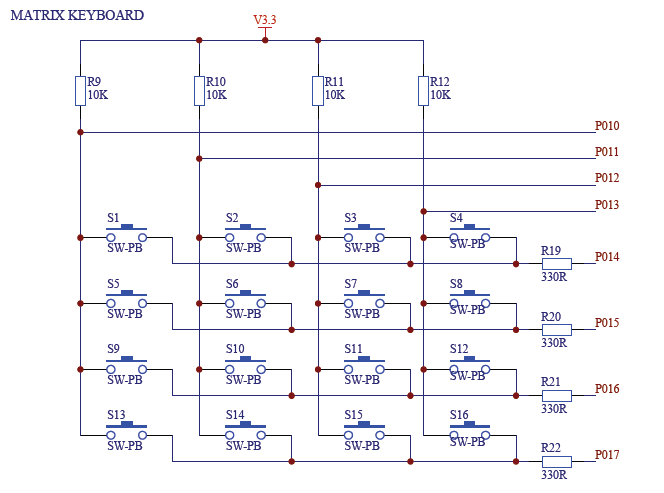
 

###


Circuit Diagrams

Circuit-Diagram-of-General-Keypad-Matrix

Project Components

  • LCD

Project Video


Filed Under: ARM


Questions related to this article?
👉Ask and discuss on Electro-Tech-Online.com and EDAboard.com forums.


Tell Us What You Think!! Cancel reply

You must be logged in to post a comment.

HAVE A QUESTION?

Have a technical question about an article or other engineering questions? Check out our engineering forums EDABoard.com and Electro-Tech-Online.com where you can get those questions asked and answered by your peers!


Featured Tutorials

  • Introduction to Brain Waves & its Types (Part 1/13)
  • Understanding NeuroSky EEG Chip in Detail (Part 2/13)
  • Performing Experiments with Brainwaves (Part 3/13)
  • Amplification of EEG Signal and Interfacing with Arduino (Part 4/13)
  • Controlling Led brightness using Meditation and attention level (Part 5/13)
  • Control Motor’s Speed using Meditation and Attention Level of Brain (Part 6/13)

Stay Up To Date

Newsletter Signup

Sign up and receive our weekly newsletter for latest Tech articles, Electronics Projects, Tutorial series and other insightful tech content.

EE Training Center Classrooms

EE Classrooms

Recent Articles

  • Key factors to optimize power consumption in an embedded device
  • EdgeLock A5000 Secure Authenticator
  • How to interface a DS18B20 temperature sensor with MicroPython’s Onewire driver
  • Introduction to Brain Waves & its Types (Part 1/13)
  • An Embedded Developer’s Perspective on IOT (Internet of Things)

Most Popular

5G 555 timer circuit 8051 ai Arduino atmega16 automotive avr bluetooth dc motor display Electronic Part Electronic Parts Fujitsu ic infineontechnologies integratedcircuit Intel IoT ir lcd led maximintegratedproducts microchip microchiptechnology Microchip Technology microcontroller microcontrollers mosfet motor powermanagement Raspberry Pi remote renesaselectronics renesaselectronicscorporation Research samsung semiconductor sensor software STMicroelectronics switch Technology vishayintertechnology wireless

RSS EDABOARD.com Discussions

  • Request for clarification question related to Segger J-Link
  • Dynamic power consumption.
  • Limits of duty cycle for ICM7555 IC?
  • pmos folded cascode vs nmos folded cascode for LDO
  • Pic 16f877A Hex file

RSS Electro-Tech-Online.com Discussions

  • Help wanted to power an AC120v induction motor ( edited from Brushless motor - thank you @SHORTBUS= )
  • How does a NOAC work?
  • Need help working with or replacing a ferrite tube
  • Trying to make a custom automated water container for my UV purifier. Can anyone help with where to begin?
  • Funny Images Thread!
Engineers Garage
  • Analog IC TIps
  • Connector Tips
  • DesignFast
  • EDABoard Forums
  • EE World Online
  • Electro-Tech-Online Forums
  • Microcontroller Tips
  • Power Electronic Tips
  • Sensor Tips
  • Test and Measurement Tips
  • 5G Technology World
  • About Us
  • Contact Us
  • Advertise

Copyright © 2022 WTWH Media LLC. All Rights Reserved. The material on this site may not be reproduced, distributed, transmitted, cached or otherwise used, except with the prior written permission of WTWH Media
Privacy Policy | Advertising | About Us

Search Engineers Garage

  • Projects and Tutorials
    • Electronic Projects
      • 8051
      • Arduino
      • ARM
      • AVR
      • PIC
      • Raspberry pi
      • STM32
    • Tutorials
    • Circuit Design
    • Project Videos
    • Components
  • Articles
    • Tech Articles
    • Insight
    • Invention Stories
    • How to
    • What Is
  • News
    • Electronic Products News
    • DIY Reviews
    • Guest Post
  • Forums
    • EDABoard.com
    • Electro-Tech-Online
    • EG Forum Archive
  • Digi-Key Store
    • Cables, Wires
    • Connectors, Interconnect
    • Discrete
    • Electromechanical
    • Embedded Computers
    • Enclosures, Hardware, Office
    • Integrated Circuits (ICs)
    • Isolators
    • LED/Optoelectronics
    • Passive
    • Power, Circuit Protection
    • Programmers
    • RF, Wireless
    • Semiconductors
    • Sensors, Transducers
    • Test Products
    • Tools
  • EE Resources
    • DesignFast
    • LEAP Awards
    • Oscilloscope Product Finder
    • White Papers
    • Webinars
  • EE Learning Center
    • Design Guides
      • WiFi & the IOT Design Guide
      • Microcontrollers Design Guide
      • State of the Art Inductors Design Guide
  • Women in Engineering