INTRODUCTION
Seven segment displays are very commonly used in meter displays, etc. In this tutorial we’ll interface seven segment display(s) to our ARM7 based microcontroller LPC2138
For those who are new to ARM refer to previous tutorial (LED Interfacing with ARM7)
DESCRIPTION
The task is to display all Numbers (0-9) and Alphabets on SSD.
LPC2138 is a 32-bit microcontroller, so while coding we’ll be dealing with IO Registers that are 32-bit wide.
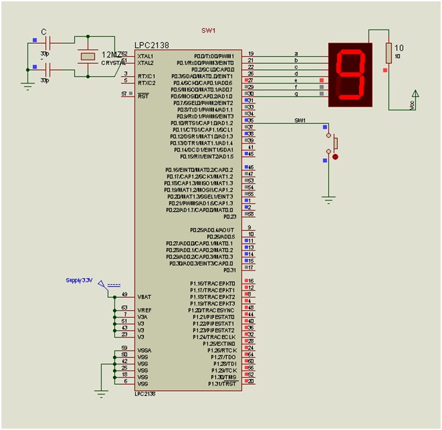
For Interfacing a 7-segment we choose P0 (P0.0 to P0.7; 8 Pins out of 32 IO Pins on Port-0)
Let’s use a common anode type display, a simple push-button switch, Resistors, etc.
a,b,c,d,e,f terminals of display are connected to P0.0 to P0.6 respectively. Common terminal is supplied with +Vcc through a current limiting resistor R.
Look-Up table
|
Disp. |
g |
f |
e |
d |
c |
b |
a |
HEX VALUE
|
|
0 |
1 |
0 |
0 |
0 |
0 |
0 |
0 |
40 |
|
1 |
1 |
1 |
1 |
1 |
0 |
0 |
1 |
79 |
|
2 |
0 |
1 |
0 |
0 |
1 |
0 |
0 |
24 |
|
3 |
0 |
1 |
1 |
0 |
0 |
0 |
0 |
30 |
|
4 |
0 |
0 |
1 |
1 |
0 |
0 |
1 |
19 |
|
5 |
0 |
0 |
1 |
0 |
0 |
1 |
0 |
12 |
|
6 |
0 |
0 |
0 |
0 |
0 |
1 |
0 |
02 |
|
7 |
1 |
1 |
1 |
1 |
0 |
0 |
0 |
78 |
|
8 |
0 |
0 |
0 |
0 |
0 |
0 |
0 |
00 |
|
9 |
0 |
0 |
1 |
0 |
0 |
0 |
0 |
10 |
|
a |
0 |
0 |
0 |
1 |
0 |
0 |
0 |
08 |
|
b |
0 |
0 |
0 |
0 |
0 |
1 |
1 |
03 |
|
c |
1 |
0 |
0 |
0 |
1 |
1 |
0 |
46 |
|
d |
0 |
1 |
0 |
0 |
0 |
0 |
1 |
21 |
First step is to generate a HEX code for each Number/Character that we want to display on SSD. This is done as in Look-up table above.
In this interfacing we are concerned only with last 7-bits of P0 (Data line for SSD; P0.0-P0.6). So we will calculate the hex value only for those bits and leave others as ‘don’t care’.
These HEX-values will be put on the port through the Port0 Register (IOPIN0)
For eg:
‘6’ will be sent to port as à IOPIN0=0x00000002
‘A’ will be sent to port as à IOPIN0=0x00000008
‘d’ will be sent to port as à IOPIN0=0x00000021
Notice the changing last 8-bits (LSB)
Details of Code:
· IODIR0 is Data direction register, which governs the direction of flow of data or more simply it decides whether the Port/Pin is Input or Output.
· IOPIN0 register is used to send data to be displayed on the pins of Port 0.
· delay() function is used to introduce a specific delay between the displayed digits/characters.
Images:

Fig. 1: Circuit Diagram of LPC2138 ARM Microcontroller and SSD Interfacing

Fig. 2: Circuit Demonstration of LPC2138 ARM Microcontroller and SSD Interfacing
Project Source Code
###
#include<lpc213x.h> // Header file for LPC devicesvoid delay(unsigned int); // Function for delayint main(){IODIR0=0x000000ff; // Set P0.0 to P0.7 as Output pinswhile(1) // Infinite loop{IOPIN0=0x00000040; // display 0delay(50);IOPIN0=0x00000079; // display 1delay(50);IOPIN0=0x00000024; // display 2delay(50);IOPIN0=0x00000030; // display 3delay(50);IOPIN0=0x00000019; // display 4delay(50);IOPIN0=0x00000012; // display 5delay(50);IOPIN0=0x00000002; // display 6delay(50);IOPIN0=0x00000078; // display 7delay(50);IOPIN0=0x00000000; // display 8delay(50);IOPIN0=0x00000010; // display 9delay(50);IOPIN0=0x00000008; // display adelay(50);IOPIN0=0x00000003; // display bdelay(50);IOPIN0=0x00000046; // display cdelay(50);IOPIN0=0x00000021; // display ddelay(50);}}void delay(unsigned int t) // definition of delay(){int i,j;for(i=0;i<t;i++)for(j=0;j<5000;j++);}###
Circuit Diagrams
Filed Under: Electronic Projects

Questions related to this article?
👉Ask and discuss on Electro-Tech-Online.com and EDAboard.com forums.
Tell Us What You Think!!
You must be logged in to post a comment.