Global Positioning System is based on satellite navigation technology. A GPS Receiver provides the accurate location of an object in terms of latitude and longitude. Accurate time calculation with respect to GMT can also be done by using GPS. For more information on different data obtained through GPS, refer GPS Receivers. Here a PIC microcontroller has been interfaced with a GPS module to extract its position information (location).
GPS provides a lot of geographical information for a particular object like its latitude, longitude, direction of travel, GMT etc. This information are assembled in a particular string format which are to be decoded by GPS modems. A GPS modem gives the output data in a following string format called as NMEA Format. A common GPS sentence ($GPGGA) has been explained below.
$GPGGA,100156.000,2650.9416,N,07547.8441,E,1,08,1.0,442.8,M,-42.5,M,,0000*71
1. A string always starts with a ‘$’ sign
2. GPGGA : Global Positioning System Fix Data
3. ‘,’ Comma indicates the separation between two values
4. 100156.000 : GMT time as 10(hr):01(min):56(sec):000(ms)
5. 2650.9416,N: Latitude 26(degree) 50(minutes) 9416(sec) North
6. 07547.8441,E: Longitude 075(degree) 47(minutes) 8441(sec) East
7. 1 : Fix Quantity 0= invalid data, 1= valid data, 2=DGPS fix
8. 08 : Number of satellites currently viewed.
9. 1.0: HDOP
10. 442.8,M : Altitude (Height above sea level in meter)
11. -42.5,M : Geoids height
12. __ , DGPS data
13. 0000 : DGPS data
14. *71 : checksum
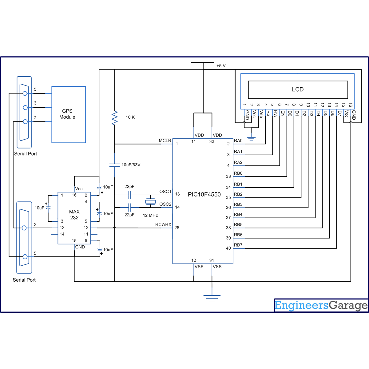
The main objective here is to find the location of the GPS Receiver in terms of latitude and longitude. The GPS module gives output data in RS232 logic level format. To convert the RS232 logic level into TTL, a line converter MAX232 has been connected between GPS module and PIC18F4550. (Also refer PIC USART) The circuit connection of GPS module with microcontroller is shown in the circuit diagram tab. The latitude and longitude data has been displayed on a 16×2 LCD interfaced to PIC.
Programming steps:
1. Set the baud rate of PIC’s USART to 4800 bps.
2. Enable the SPEN and CREN bits (RCSTA register).
3. Receive the Serial data and compare with the string ‘$GPGGA,’ byte by byte.
4. Wait for comma (,) as string gets matched.
5. Store the data which appears after the above comma into a string which will be the Latitude.
6. After another comma (,), store the data into another string which will be the Longitude.
7. Display both Latitude and Longitude data on LCD.
8. Repeat the steps 3 to 7 to update the GPS module’s positions on LCD.
Project Source Code
###


// Program to Interface GPS with PIC18F4550 Microcontroller
#define FREQ 12000000
#define baud 4800
#define spbrg_value (((FREQ/64)/baud)-1)
#define rs LATA.F0
#define rw LATA.F1
#define en LATA.F2
#define lcdport LATB

unsigned char rx_data();
void lcd_ini();
void lcdcmd(unsigned char);
void lcddata(unsigned char);

unsigned char longi_data[12];
unsigned char lati_data[12];
unsigned char data,value=0;
unsigned int i=0,pos;

void main()
{
TRISB=0; // Set Port B as output port
LATB=0;
TRISA=0;
LATA=0;
SPBRG=spbrg_value; // Fill SPBRG register to set the baud rate
RCSTA.SPEN=1; // To activate serial port (Tx and Rx pins)
RCSTA.CREN=1; // To enable continuous reception
lcd_ini();
while(1)
{
data=rx_data(); // Check the string '$GPGGA,'
if(data=='$')
{
data=rx_data();
if(data=='G')
{
data=rx_data();
if(data=='P');
{
data=rx_data();
if(data=='G');
{
data=rx_data();
if(data=='G')
{
data=rx_data();
if(data=='A')
{
data=rx_data();
if(data==',')
{
data=rx_data();
while(data!=',')
data=rx_data();
for(i=0;data!='N';i++)
data=rx_data();
lati_data[i]=data; // Store the Latitude data
}
data=rx_data();
if(data==',')
{
for(i=0;data!='E';i++)
{
data=rx_data();
longi_data[i]=data; // Store the Longitude data
}
}
i=0;
lcdcmd(0x80);
while(i<11)
{
lcddata(lati_data[i]); // Print the Latitude data
i++;
}
i=0;
lcdcmd(0xC0);
while(i<12)
{
lcddata(longi_data[i]); // Print the Longitude data
i++;
}
}
}
}
}
}
}
}
Delay_ms(1000);
for(i=0;i<12;i++)
{
data=0;
lati_data[i]=0;
longi_data[i]=0;
}
}
}

unsigned char rx_data(void)
{
while(PIR1.RCIF==0); // Wait until RCIF gets low
return RCREG; // Store data in Reception register
}

void lcd_ini()
{
lcdcmd(0x38); // Configure the LCD in 8-bit mode, 2 line and 5x7 font
lcdcmd(0x0C); // Display On and Cursor Off
lcdcmd(0x01); // Clear display screen
lcdcmd(0x06); // Increment cursor
lcdcmd(0x80); // Set cursor position to 1st line, 1st column
}

void lcdcmd(unsigned char cmdout)
{
lcdport=cmdout; //Send command to lcdport=PORTB
rs=0;
rw=0;
en=1;
Delay_ms(10);
en=0;
}

void lcddata(unsigned char dataout)
{
lcdport=dataout; //Send data to lcdport=PORTB
rs=1;
rw=0;
en=1;
Delay_ms(10);
en=0;
}

###
Circuit Diagrams
Project Components
Project Video
Filed Under: PIC Microcontroller.
Filed Under: PIC Microcontroller.

Questions related to this article?
👉Ask and discuss on EDAboard.com and Electro-Tech-Online.com forums.
Tell Us What You Think!!
You must be logged in to post a comment.