The ARM7 (LPC2148) is a 32 bit microcontroller and it supports two serial ports. We can program ARM7 using FlashMagic utility which is free software used to transfer HEX file in to the Microcontroller.
What are the requirements for interfacing GSM (SIM300) module with ARM7 microcontroller? We should have serial cable, one ARM7 board, GSM module and a PC with Keil version 4 cross compiler.
Let’s look at the basics of GSM.
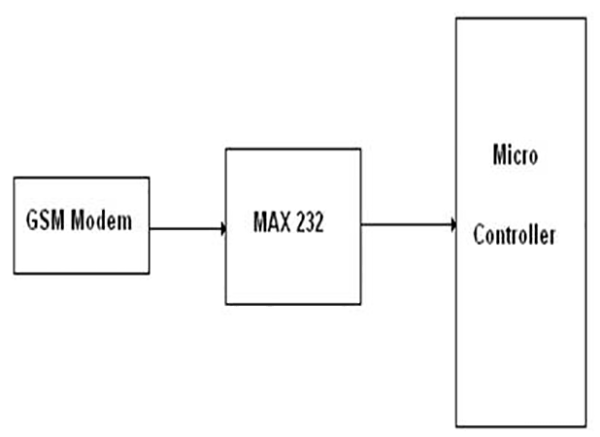
Text messages may be sent through the modem by interfacing only three signals of the serial interface of modem with microcontroller i.e., TxD, RxD and GND. In this scheme, RTS and CTS signals of serial port interface of GSM Modem are connected with each other.
The transmit and receive signals of the microcontroller serial port are connected to the corresponding signals of the serial interface of GSM module
The SMS message in text mode can contain only up to 140 characters. It depends upon the amount of information collected from GPS Engine that you need at the base station for tracking a vehicle or a person.

Fig. 1: Overview of LPC2148 and GSM Modem Interfacing
Fig 1 Interfacing GSM with LPC2148
Display text in mobile from LPC2148 kit by using GSM module through UART. The entire LPC2148 kit contains two serial interfaces that are UART0 & UART1. Here we are using UART0 for programming kit as well as for interfacing GSM module.
Pin Assignment with LPC2148

Fig. 2: Table showing circuit connections of LPC2148 with UART Port
The Interfacing GSM module with LPC2148 program is very simple and straight forward, which send a message to mobiles from LPC2148 Primer Board through GSM module by using UART0. Some delay is occurring when a single data is sent to mobile through UART. C programs are written in Keil software. The baud rate of microcontroller is 9600.
C Program to send a message from LPC2148
In Keil, if you want to develop or debug the project without any hardware setup then you must compile the code for generating HEX file. In debugging mode, you have to check the port output without LPC2148 Primer Board.
Testing the GSM with LPC2148
If you are not reading any text from UART0, then just check the jumper connections and ensure that the serial cable is working. Otherwise, check the code with debugging mode in Keil. If you want to see more details about debugging just see the videos in the link below..
As homework you can wonder about LCD functions in the code.
Project Source Code
###
#define CR 0x0D
#include <LPC21xx.H>
#include <stdio.h>
void getstring(unsigned char *);
int getchar (void) /* Read character from Serial Port */
void status_ok(void);
void Serial_Init(void);
void delay(unsigned int n);
void main(void) //This is main code
{
unsigned int cnt=0x80,m;
char xx;
Serial_Init();
delay(50);
while(1) //infinite loop super loop
{
printf("ATr"); // AT COMMAND FOR INITIALING
status_ok();
printf("AT+IPR=9600r"); // AT COMMAND FOR BAUD RATE
status_ok();
printf("AT+CMGR=2r"); // Reading the message detail
// at Index 1 with phone number, data and time
status_ok();
delay(250);
printf("ATD9790550124;r");//AT COMMAND FOR CALL DIALING
delay(250);
status_ok();
delay(500);
delay(500);
delay(500);
delay(500);
delay(500);
delay(500);
printf("ATHr"); // AT COMMAND FOR CALL DISCONNECTING
delay(250);
status_ok();
delay(500);
delay(500);
printf("ATDLr"); // AT COMMAND FOR REDIALING
delay(250);
status_ok();
delay(500);
delay(500);
printf("ATHr"); // AT COMMAND FOR ANSWERING THE CALL
delay(250);
status_ok();
delay(500);
delay(500);
}
}
void getstring(unsigned char *array)
{
unsigned char temp=0, i=0;
do
{
temp = getchar();
*array++ = temp;
}
while((temp != 'r') && (temp != 'n'));
*array = '�';
}
int getchar (void) /* Read character from Serial Port */
{
while (!(U0LSR & 0x01));
return (U0RBR);
}
void status_ok(void)
{
getstring(y);
while(!(strstr(y,"OK"))) getstring(y);
pointr = strstr(y,"OK");
lcd_cmd(0xc0);
lcd_data(*pointr++);
lcd_data(*pointr);
delay(500);
lcd_cmd(0x01);
}
void Serial_Init(void)
{
PINSEL0 |= 0X00000005; //Enable Txd0 and Rxd0
U0LCR = 0x00000083; //8-bit data, no parity, 1-stop bit
U0DLL = 0x00000061; //for Baud rate=9600,DLL=82
U0LCR = 0x00000003; //DLAB = 0;
}
void delay(unsigned int n)
{
unsigned int i,j;
for(i=0;i<n;i++)
{
for(j=0;j<12000;j++)
{;}
}
}
//end of program
###
Filed Under: Electronic Projects


Questions related to this article?
👉Ask and discuss on Electro-Tech-Online.com and EDAboard.com forums.
Tell Us What You Think!!
You must be logged in to post a comment.