GSM is widely used mobile communication architecture used in most of the countries. This project demonstrates the interfacing of microcontroller AT89C51 with HyperTerminal and GSM module. It aims to familiarize with the syntax of AT Commands and their Information Response and Result Codes. The ASCII values of characters in the Information Response, Result Codes and their syntax can be monitored by an LED array. For the basic concepts, working and operation of AT commands and GSM module refer GSM/GPRS Module.
The project explains interfacing of the AT89C51 microcontroller with the GSM module and the HyperTerminal. HyperTerminal is a Windows application. The AT commands are sent by the HyperTerminal to the GSM module. The Information Response and/or Result Codes are received at the microcontroller and retransmitted to the HyperTerminal by the controller.
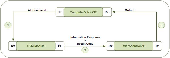
A GSM module has an RS232 interface for serial communication with an external peripheral. In this case, the transmit pin (Tx) of the computer’s Serial port is connected with the receive pin (Rx) of the GSM module’s RS-232 interface. The transmit pin (Tx) of the RS-232 of GSM module is connected to receive pin (Rx) of microcontroller’s serial transmission pin. And the serial transmit pin of the microcontroller is connected to the receive pin of the computer’s Serial port. Therefore the commands and their results are transmitted and received in a triangular fashion as depicted below.

Fig. 2: Block Diagram Of GSM Module’s RS-232 Interface
[In subsequent projects (see MC075 & MC076), the HyperTerminal will be replaced by the microcontroller itself; thus avoiding the need of using a Computer to establish an interface. This would lead to an independent GSM based system.]
The microcontroller is programmed to receive and transmit data at a baud rate of 9600. For more details on setting the baud rate of microcontroller, refer serial communication with 8051.
The microcontroller is programmed to receive and transmit data at a baud rate of 9600. For more details on setting the baud rate of microcontroller, refer serial communication with 8051.
The controller can receive data signals either by polling or by making use of serial interrupt (ES). Serial interrupt has been explained in interrupt programming. In polling, the controller continuously scans serial port for incoming data from the GSM module.
In this project, interrupt has been used for monitoring and controlling the flow of data by the controller instead of the polling method.
Project Source Code
###
// Program to interface GSM Module with 8051 microcontroller (AT89C51) using PC #include<reg51.h> unsigned char str; void init_serial() // Initialize serial port { TMOD=0x20; // Mode=2 TH1=0xfd; // 9600 baud SCON=0x50; // Serial mode=1 ,8-Bit data,1 Stop bit ,1 Start bit , Receiving on TR1=1; // Start timer } void transmit_data(unsigned char str) // Function to transmit data through serial port { SBUF=str; // Store data in sbuf while(TI==0); // Wait till data transmit TI=0; } void receive_data() interrupt 4 // Function to recieve data serialy from RS232 into microcontroller { str=SBUF; // Read sbuf RI=0; transmit_data(str); // Transmit to HyperTerminal } void main() { init_serial(); // Initialize serial port IE=0x90; while(1); }###
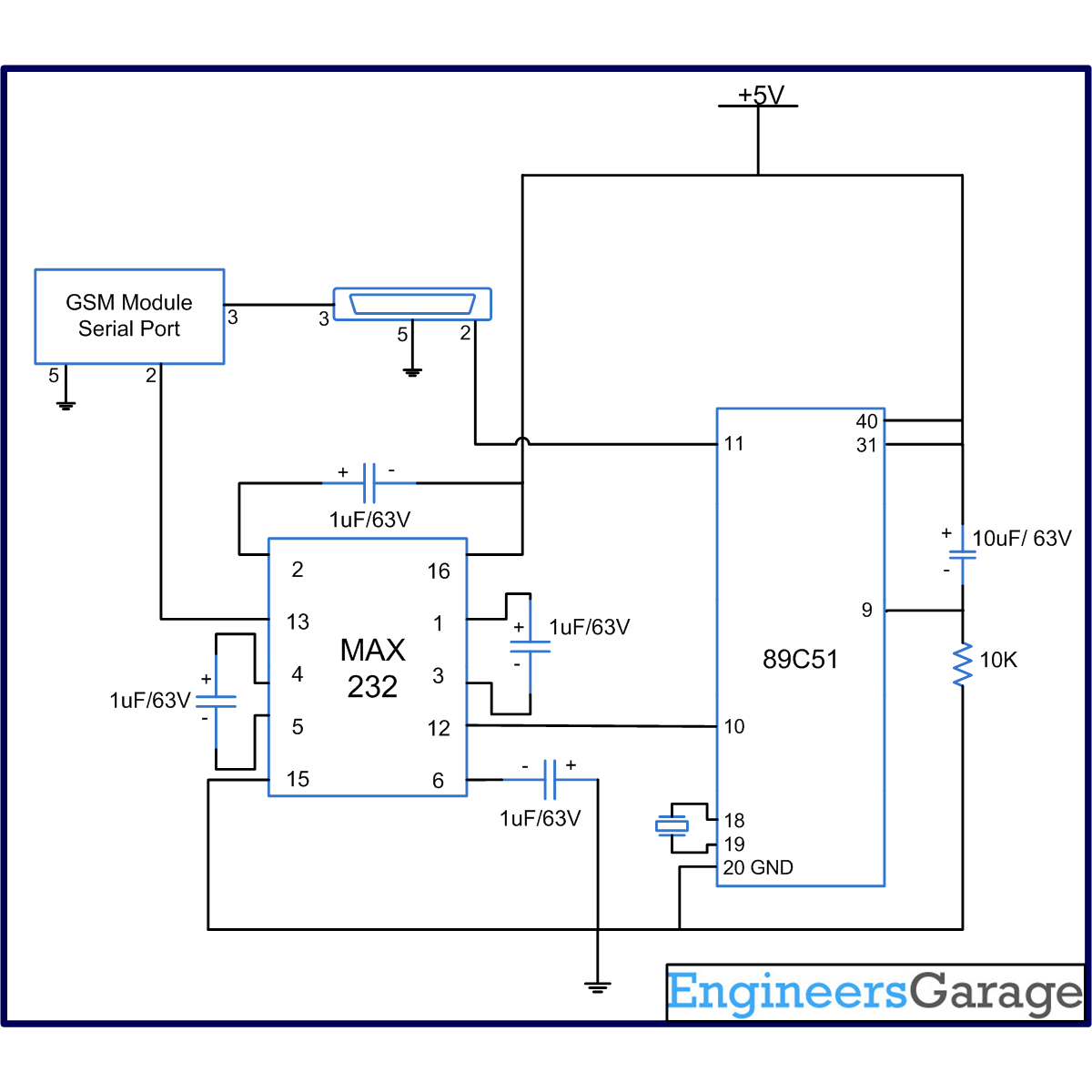
Circuit Diagrams
Project Components
Project Video
Filed Under: 8051 Microcontroller.
Filed Under: 8051 Microcontroller.


Questions related to this article?
👉Ask and discuss on Electro-Tech-Online.com and EDAboard.com forums.
Tell Us What You Think!!
You must be logged in to post a comment.