Engineers Garage

  • Electronics Projects and Tutorials
    • Electronic Projects
      • Arduino Projects
      • AVR
      • Raspberry pi
      • ESP8266
      • BeagleBone
      • 8051 Microcontroller
      • ARM
      • PIC Microcontroller
      • STM32
    • Tutorials
      • Audio Electronics
      • Battery Management
      • Brainwave
      • Electric Vehicles
      • EMI/EMC/RFI
      • Hardware Filters
      • IoT tutorials
      • Power Tutorials
      • Python
      • Sensors
      • USB
      • VHDL
    • Circuit Design
    • Project Videos
    • Components
  • Articles
    • Tech Articles
    • Insight
    • Invention Stories
    • How to
    • What Is
  • News
    • Electronic Product News
    • Business News
    • Company/Start-up News
    • DIY Reviews
    • Guest Post
  • Forums
    • EDABoard.com
    • Electro-Tech-Online
    • EG Forum Archive
  • DigiKey Store
    • Cables, Wires
    • Connectors, Interconnect
    • Discrete
    • Electromechanical
    • Embedded Computers
    • Enclosures, Hardware, Office
    • Integrated Circuits (ICs)
    • Isolators
    • LED/Optoelectronics
    • Passive
    • Power, Circuit Protection
    • Programmers
    • RF, Wireless
    • Semiconductors
    • Sensors, Transducers
    • Test Products
    • Tools
  • Learn
    • eBooks/Tech Tips
    • Design Guides
    • Learning Center
    • Tech Toolboxes
    • Webinars & Digital Events
  • Resources
    • Digital Issues
    • EE Training Days
    • LEAP Awards
    • Podcasts
    • Webinars / Digital Events
    • White Papers
    • Engineering Diversity & Inclusion
    • DesignFast
  • Guest Post Guidelines
  • Advertise
  • Subscribe

How to interface GSM Module with PIC18F4550 Microcontroller- (Part 17/25)

By Amit Joshi July 30, 2011

The Global System for Mobile (GSM) communication is the Second Generation of mobile technology. Although the world is moving towards Third and Fourth generation but GSM has been the most successful and widespread technology in the communication sector. GSM technology paved a new way for mobile communication.
This project explains the interfacing of a GSM Module with a PIC microcontroller. It also covers a way to dial a particular GSM mobile number as well as send a message to it using AT Commands with the help of PIC18F4550.


As explained earlier (refer GSM interfacing with 8051), a line converter MAX232 is employed to convert the RS232 logic data of GSM Module to TTL logic so that it can be processed by the microcontroller. In this project, instead of RS232 logic data, TTL logic output has been taken and thus PIC18F4550 has been directly connected with GSM Modem without any line converter in between. The following diagram shows the TTL input and output of GSM modem used.
 
TTL output Pins of GSM Module used in Interfacing
Fig. 2: TTL output Pins of GSM Module used in Interfacing

Objectives:

This project has following objectives which are fulfilled using AT Commands:

1.      Test the simple AT Command.
2.      Find out the IMEI number of the GSM Modem.
3.      Connect a call to a GSM mobile number (Dial a number).
4.      Send a text message to a mobile number.
 
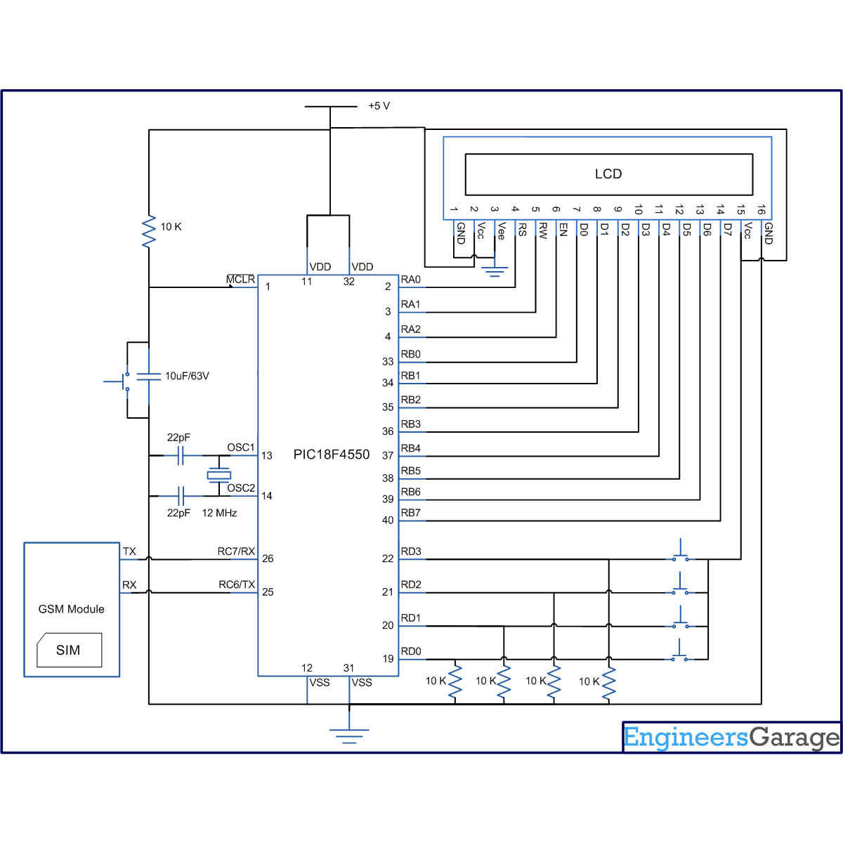
The provision of these four operations has been provided by means of four tactile switches. Each switch corresponds to each of the above functions. AT Commands used to perform the above operations have been given below along with their output. (For complete list of AT Commands supported by GSM Modem, refer the list in tutorial on AT Commands.

1. Test the simple AT Command.


AT     (Enter)


OK


2. Find out the IMEI number of the GSM modem.

AT+GSN     (Enter)
xxxxxxxxxxxxxxx(15- digit unique IMEI number) 

OK


3. Dial a number.
ATDXXXXXXXXXX;     (Enter) (10-digit mobile number)


OK


4. Send a text message.
AT+CMGS= “XXXXXXXXXX”     (Enter) (10-digit mobile number)
>Hello ^z                    (Enter message after ‘>’ and use Ctrl+z to terminate the message)

 
The program for the controller is written in a manner so that when a particular switch is pressed, its corresponding command will be called to execute. LCD is also interfaced with PIC18F4550 to display the results. The circuit connections of GSM module, LCD and switches with controller are shown in the circuit diagram tab. Check the video for the execution of this project.
 
Programming Steps:
1. Store all AT commands into strings.
2. Set the baud rate of microcontroller to 9600bps.
3. Enable serial port. (Refer USART with PIC)
4. Enable the global and peripheral interrupt bits of the INTCON register.
5. Configure Port D as input port.
6. Use if condition to detect the pressed switch.
7. As switch is pressed, process the corresponding AT command and transmit via USART.
8. Reception interrupt method is used to store the GSM output data into an array.
9. Display the stored value on the LCD. (Refer displaying text on LCD using PIC)
 

Project Source Code

###

//Program to interface GSM Modem with PIC18F4550 Microcontroller
//This code takes four choices as four inputs

//Choice 1 : Test the simple AT Command.
//Choice 2 : Find out the IMEI number of the GSM Modem.
//Choice 3 : Connect a call to a GSM mobile number.
//Choice 4 : Send a text message to a mobile number.

#define FREQ 12000000
#define baud 9600
#define spbrg_value (((FREQ/64)/baud)-1)
#define rs LATA.F0
#define rw LATA.F1
#define en LATA.F2
#define lcdport LATB

void tx_data(unsigned char);
unsigned char rx_data();
void lcd_ini();
void lcdcmd(unsigned char);
void lcddata(unsigned char);
void gsm_cmd(unsigned char *);
void output(void);

unsigned char value=0;
int i=0,j,k,temp,flag,choice;
unsigned char *starting_text="Enter choice=";
unsigned char *dial_text="Dialing...";
unsigned char *at_cmd="AT";
unsigned char *imei_cmd="AT+GSN";
unsigned char *call_cmd="ATD9xxxxxxxxx;"; // Provide a 10-Digit Mobile Number
unsigned char *sms_format="AT+CMGF=1";
unsigned char *sms_write="AT+CMGS="xxxxxxxxxx""; // 10-Digit Mobile Number
unsigned char *sms="Hello";
unsigned char *sms_report="SMS Sent...";
unsigned char sms_terminate=0x1A;
unsigned char enter=0x0D;
unsigned char *data;

void main()
{
TRISB=0; // Set Port B as output port
LATB=0;
TRISA=0;
LATA=0;
TRISD=0xFF;
LATD=0;
SPBRG=spbrg_value; // Fill SPBRG register to set the baud rate
RCSTA.SPEN=1; // To activate serial port (Tx and Rx pins)
TXSTA.TXEN=1; // Activate Transmissiom
RCSTA.CREN=1; // Activate Reception
PIE1.RCIE=1; // Enable Reception interrupt
INTCON.GIE=1; // Enable Global interrupt
INTCON.PEIE=1; // Enable Peripheral interrupt

lcd_ini();
while(1)
{
k=0;
lcdcmd(0x80);
while(starting_text[k]!='')
{
lcddata(starting_text[k]);
k++;
}

//Check inputs

//Choice 1
if(PORTD.F0)
{
gsm_cmd(at_cmd);
output();
Delay_ms(1000);
}


//Choice 2
if(PORTD.F1)
{
gsm_cmd(imei_cmd);
output();
Delay_ms(1000);
}

//Choice 3
if(PORTD.F2)
{
gsm_cmd(call_cmd);
output();
Delay_ms(1000);
}

//Choice 4
if(PORTD.F3)
{
gsm_cmd(sms_format);
output();
Delay_ms(1000);

gsm_cmd(sms_write);
output();
Delay_ms(1000);

gsm_cmd(sms);
output();
tx_data(0x1A);
Delay_ms(1000);
}

}

}

void gsm_cmd(unsigned char *string)
{
i=0;j=0;
while(string[i]!='')
{
temp=0;
if(string[i]==0x5C) // Not to send '' cahracter
i++;
tx_data(string[i]); // Send by serial communication
i++;
while(temp!=1);
}
temp=0;
tx_data(enter); // Send ASCII code for 'Enter' key
while(temp!=1);
}

void output(void) // To print data on LCD
{
lcdcmd(0x01);
i=-1;flag=0;
while(i<j)
{
if(flag>1)
{
flag=0;
Delay_ms(500);
lcdcmd(0x01);
lcdcmd(0x80);
}
if(data[i]==0x0A) // This condition is to avoid double Enter

// during execution of a command
{
flag++;
lcdcmd(0xc0);
}
if(data[i]=='>'||data[i]=='"') // Not to print this character
{
i++;
lcdcmd(0xc0);
}
if(data[i]!=0x0D&&data[i]!=0x0A&&data[i]!=0x1A) // Condition to print the data
// except 'Enter','New line' and 'Submit'

{
lcddata(data[i]);
i++;
}
else
i++;
Delay_ms(300);
}
lcdcmd(0x01);
}

void tx_data(unsigned char serial_data) // Transmit data function
{
TXREG=serial_data;
while(PIR1.TXIF==0);
}


void interrupt()
{
data[j]=RCREG; // Store the data into array when Reception interrupt occurs
value=RCREG;
j++;
temp=1;
}

void lcd_ini()
{
lcdcmd(0x38); // Configure the LCD in 8-bit mode, 2 line and 5x7 font
lcdcmd(0x0C); // Display On and Cursor Off
lcdcmd(0x01); // Clear display screen
lcdcmd(0x06); // Increment cursor
lcdcmd(0x80); // Set cursor position to 1st line, 1st column
}

void lcdcmd(unsigned char cmdout)
{
lcdport=cmdout; //Send command to lcdport=PORTB
rs=0;
rw=0;
en=1;
Delay_ms(10);
en=0;
}

void lcddata(unsigned char dataout)
{
lcdport=dataout; //Send data to lcdport=PORTB
rs=1;
rw=0;
en=1;
Delay_ms(10);
en=0;
}

###


Circuit Diagrams

Circuit-Diagram-of-How-to-interface-GSM-with-PIC-Microcontroller

Project Components

  • LCD
  • PIC18F4550

Project Video


Filed Under: PIC Microcontroller
Tagged With: call, gsm, message, microcontroller, pic18f4550
 

Next Article

← Previous Article
Next Article →

Questions related to this article?
👉Ask and discuss on Electro-Tech-Online.com and EDAboard.com forums.


Tell Us What You Think!! Cancel reply

You must be logged in to post a comment.

EE TECH TOOLBOX

“ee
Tech Toolbox: Internet of Things
Explore practical strategies for minimizing attack surfaces, managing memory efficiently, and securing firmware. Download now to ensure your IoT implementations remain secure, efficient, and future-ready.

EE Learning Center

EE Learning Center
“engineers
EXPAND YOUR KNOWLEDGE AND STAY CONNECTED
Get the latest info on technologies, tools and strategies for EE professionals.

HAVE A QUESTION?

Have a technical question about an article or other engineering questions? Check out our engineering forums EDABoard.com and Electro-Tech-Online.com where you can get those questions asked and answered by your peers!


RSS EDABOARD.com Discussions

  • How can I get the frequency please help!
  • Elektronik devre
  • 12VAC to 12VDC 5A on 250ft 12AWG
  • SPI speed pic18f66j15
  • Antiparallel Schottky Diodes VDI-Load Pull

RSS Electro-Tech-Online.com Discussions

  • Actin group needed for effective PCB software tutorials
  • how to work on pcbs that are thick
  • compatible eth ports for laptop
  • How to repair this plug in connector where wires came loose
  • Kawai KDP 80 Electronic Piano Dead

Featured – Designing of Audio Amplifiers part 9 series

  • Basics of Audio Amplifier – 1/9
  • Designing 250 Milli Watt Audio Power Amplifier – 2/9
  • Designing 1 Watt Audio Power Amplifier – 3/9
  • Designing a Bass Boost Amplifier – 4/9
  • Designing a 6 Watt Car Audio Amplifier – 5/9
  • Design a low power amplifier for headphones- 6/9

Recent Articles

  • ITG Electronics releases gate drive transformers with 200 – 450 V DC capability
  • Stackpole introduces HCJ jumpers with 70.7 amp continuous current capability
  • Infineon releases MCU with 128K flash and multi-sense capabilities
  • ST introduces 600V GaN gate drivers with 300 ns start-up time
  • ABLIC releases S-19116 automotive voltage detector with 6.8μs response time

EE ENGINEERING TRAINING DAYS

engineering

Submit a Guest Post

submit a guest post
Engineers Garage
  • Analog IC TIps
  • Connector Tips
  • Battery Power Tips
  • DesignFast
  • EDABoard Forums
  • EE World Online
  • Electro-Tech-Online Forums
  • EV Engineering
  • Microcontroller Tips
  • Power Electronic Tips
  • Sensor Tips
  • Test and Measurement Tips
  • 5G Technology World
  • Subscribe to our newsletter
  • About Us
  • Contact Us
  • Advertise

Copyright © 2025 WTWH Media LLC. All Rights Reserved. The material on this site may not be reproduced, distributed, transmitted, cached or otherwise used, except with the prior written permission of WTWH Media
Privacy Policy

Search Engineers Garage

  • Electronics Projects and Tutorials
    • Electronic Projects
      • Arduino Projects
      • AVR
      • Raspberry pi
      • ESP8266
      • BeagleBone
      • 8051 Microcontroller
      • ARM
      • PIC Microcontroller
      • STM32
    • Tutorials
      • Audio Electronics
      • Battery Management
      • Brainwave
      • Electric Vehicles
      • EMI/EMC/RFI
      • Hardware Filters
      • IoT tutorials
      • Power Tutorials
      • Python
      • Sensors
      • USB
      • VHDL
    • Circuit Design
    • Project Videos
    • Components
  • Articles
    • Tech Articles
    • Insight
    • Invention Stories
    • How to
    • What Is
  • News
    • Electronic Product News
    • Business News
    • Company/Start-up News
    • DIY Reviews
    • Guest Post
  • Forums
    • EDABoard.com
    • Electro-Tech-Online
    • EG Forum Archive
  • DigiKey Store
    • Cables, Wires
    • Connectors, Interconnect
    • Discrete
    • Electromechanical
    • Embedded Computers
    • Enclosures, Hardware, Office
    • Integrated Circuits (ICs)
    • Isolators
    • LED/Optoelectronics
    • Passive
    • Power, Circuit Protection
    • Programmers
    • RF, Wireless
    • Semiconductors
    • Sensors, Transducers
    • Test Products
    • Tools
  • Learn
    • eBooks/Tech Tips
    • Design Guides
    • Learning Center
    • Tech Toolboxes
    • Webinars & Digital Events
  • Resources
    • Digital Issues
    • EE Training Days
    • LEAP Awards
    • Podcasts
    • Webinars / Digital Events
    • White Papers
    • Engineering Diversity & Inclusion
    • DesignFast
  • Guest Post Guidelines
  • Advertise
  • Subscribe