This is special section of web-site. In this section we will learn how we can display a character or a message on LCD display. You can choose any standard LCD available in market. I have experimented with 20×2 LCD. It means LCD has 2 lines of 20 characters each. Many other LCDs like 16×2, 24×2, 32×2, 20×4 etc. are available. Functionally all these LCDs are same. To develop a protocol to interface this LCD with 89C51 first we have to understand how they functions.
These displays contain two internal byte-wide registers, one for command and second for characters to be displayed. There are three control signals called R/W, DI/RS and En. The table given below will tell you what the use of these three signals is.
|
Control Signals |
It’s function |
|
R/W |
= 0 Writes character in display |
|
= 1 Reads from display |
|
|
RS/DI |
= 0 Selects command register |
|
= 1 Selects Data register to display character |
|
|
En |
= 0 Disables the display |
|
= 1 Enables the display |
By making RS/DI signal 0 you can send different commands to display. These commands are used to initialized LCD, to select display pattern, to shift cursor or screen etc. The different commands and their functions are as given below
|
Bits |
Function |
|||||||||
|
RS/DI |
R/W |
D7 |
D6 |
D5 |
D4 |
D3 |
D2 |
D1 |
D0 |
|
|
0 |
0 |
0 |
0 |
0 |
0 |
0 |
0 |
0 |
1 |
Clear LCD memory, Home cursor |
|
0 |
0 |
0 |
0 |
0 |
0 |
0 |
0 |
1 |
0 |
Clear and Home cursor only |
|
0 |
0 |
0 |
0 |
0 |
0 |
0 |
1 |
I/O |
s |
s = 1/0 : Shift screen/cursor, I/O = 1/0 : shift R/L |
|
0 |
0 |
0 |
0 |
0 |
0 |
1 |
D |
C |
B |
D = 1/0 : Screen On/Off. C = 1/0 : cursor On/Off. B = 1/0 : Cursor blink/no blink |
|
0 |
0 |
0 |
0 |
0 |
1 |
S/C |
R/L |
0 |
0 |
S/C = 1/0 : Screen / Cursor. R/L = 1/0 : Shift one space right / left |
|
0 |
0 |
0 |
0 |
1 |
DL |
N |
F |
0 |
0 |
D/L = 1/0 : 8/4 bits per character. N = 1/0 : 2/1 rows of char. F = 1/0 : 5×10/5×7 dots/char. |
|
0 |
0 |
0 |
1 |
Char address |
Write to char. RAM address after this |
|||||
|
0 |
0 |
1 |
Display data address |
Writes to display RAM address after this |
||||||
|
|
1 |
BF |
Current address |
BF = 1/0 : display is busy/not busy |
||||||
|
1 |
0 |
Character type |
Write byte to last RAM chosen |
|||||||
|
1 |
1 |
Character type |
Read byte from last RAM chosen |
|||||||
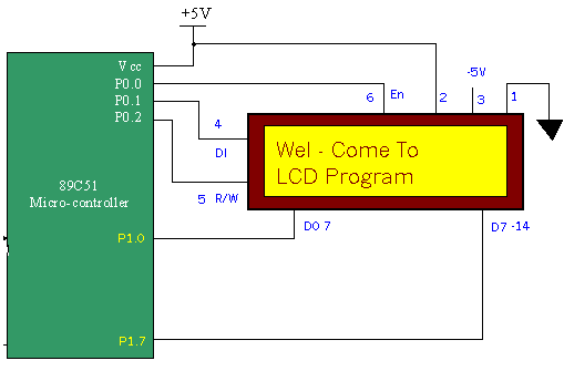
The figure in Circuit Diagram Tab shows connections of LCD with 89C51. All the data lines of LCD are connected with port P1. En pin is connected with P0.0, DI (RS) is connected with P0.1 and R/W pin is connected with P0.2.
Next the program is given in 8051 assembly language with necessary comments that can display a message or single character on screen.
Project Source Code
###
com equ 0fch ; command follows this header
dat equ 0fdh ; Data follows this header
eof equ 0feh ; End of messageorg 00h
mov dptr,#2000h ; Initilize LCD and display message
acall msg ; "Wel - Come To
mov a,#c0h ; Go to the next line
acall cmmd
mov a,#'L' ; and display character 'L'
acall dis
mov a,#'C' ; and display character 'C'
acall dis
mov a,#'D' ; and display character 'D'
acall dis
mov dptr,#3000h ; display word 'program' in next line
acall msg ; after character 'D'.
here: sjmp here ; continue loop
msg:
acall ready ; wait until display is busy
clr a
movc a,@a+dptr ; get the character
inc dptr ; point to next character
cjne a,#eof,cmd ; if end of message then
ret ; return from sub routine
cmd:cjne a,#com,data ; if command then DI (RS) = 0
clr p0.1
sjmp msg ; go until done
data:cjne a,#dat,send ; if data then DI (RS) = 1
setb p0.1
sjmp msg ; go until done
send: mov p1,a ; send data/command to display
clr p0.2 ; write enable
setb p0.0 ; strobe character to display
clr p0.0
sjmp msg ; go until done
cmmd:
acall ready ; wait until display is busy
mov p1,a ; command chara. in p1
clr p0.1 ; select com. register
clr p0.2 ; write enable
setb p0.0 ; strobe the chara.
clr p0.0
ret
dis:
acall ready ; wait until display is busy
mov p1,a ; data chara. in p1
setb p0.1 ; select data register
clr p0.2 ; write enable
setb p3.7 ; strobe the chara.
clr p3.7
ret
ready:
mov r7,p0 ; save content of P0
clr p0.0 ; disable display
clr p0.1 ; select command register
setb p0.2 ; read enable
wait:clr p0.0 ; strobe display
setb p0.0 ; read busy status of display
jb p1.7,wait ; wait for busy
clr p3.7
mov p0,r7 ; restore content of P0
ret
org 2000h ; messages are stored at
db com ; locations 2000h and 3000h
db 3ch
db 0fh
db 01h
db dat
db 'Wel-Come To'
db eoforg 3000h
db com
db 0c5h
db dat
db 'Program'
db eofend
###
Circuit Diagrams
Filed Under: Electronic Projects

Questions related to this article?
👉Ask and discuss on EDAboard.com and Electro-Tech-Online.com forums.
Tell Us What You Think!!
You must be logged in to post a comment.