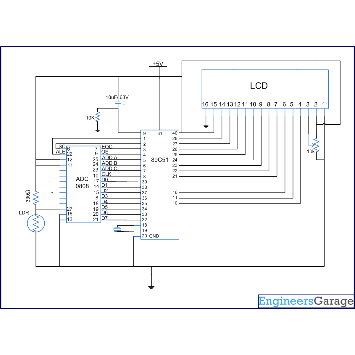
ADC0808 is an 8-bit resolution IC with eight input pins. LDR is used to provide the analog input. The output of the LDR is displayed on a 16×2 LCD. A clock of frequency 500 KHz is generated using Timer0 in the interrupt mode. To enable the interrupt, the value of the register IE is set to 0x82 (Refer interfacing ADC 0808 with interrupt clock).
The output pins of ADC are connected to the port P0 of the AT89C51. The pin10 of the ADC is connected to pin8 (P1.7) of the controller for clock input. ALE, pin22 of the ADC is connected to pin1 (P1.0) of controller. OE, pin9 of the ADC is connected to pin4 (P1.3) of controller. SC, pin6 of the ADC is connected to pin2 (P1.1) of the controller. EOC, pin number 7 is connected to pin 3 (P1.2) of controller. Selector pins A (25), B (24) and C (24) of ADC are connected to the pins 4, 5 and 6 of the controller respectively.
Port P2 (pins 21-28) of controller is used to send the data to the LCD (pins 7-14). RS (pin4) of LCD is connected to P3.0 (pin 10) of controller. R/W (pin5) of LCD is connected to P3.1 (pin11) of the controller. Enable pin, EN, pin6 of LCD will connect to P3.6 of controller (Refer LCD interfacing).
The controller continuously monitors the output of the ADC. The output of the LDR varies with the intensity of light. The value ADC output varies from 0 to 255. The output of ADC is converted to decimal form and then displayed on the LCD (Refer displaying number on LCD). If the output of any of the LDR varies, the corresponding change is reflected on LCD screen.
Project Source Code
###
// Program to interface LDR using ADC 0808. The output of LDR is displayed on LCD. Controller interrupt is used to generate the clock for driving ADC 0808. #include<reg51.h> sbit ale=P1^0; //address latch enable sbit oe=P1^3; //output enable sbit sc=P1^1; //start conversion sbit eoc=P1^2; //end of conversion sbit clk=P1^7; // clock sbit ADD_A=P1^4; // Address pins for selecting input channels. sbit ADD_B=P1^5; sbit ADD_C=P1^6; sfr lcd_data_pin=0xA0; //P2 port sbit rs=P3^0; sbit rw=P3^1; sbit en=P3^6; sfr input_port=0x80; //P0 port unsigned int bitvalue,decimal_value,key,left_value,value,number,ascii1,ascii2,ascii3,flag,key1; void timer0() interrupt 1 // Function to generate clock of frequency 500KHZ using Timer 0 interrupt. { clk=~clk; } void delay(unsigned int count) // Function to provide time delay in msec. { int i,j; for(i=0;i<count;i++) for(j=0;j<1275;j++); } void lcd_command(unsigned char comm) //Function to send command to LCD. { lcd_data_pin=comm; en=1; rs=0; rw=0; delay(10); en=0; } void lcd_data(unsigned char disp) //Function to send data to LCD. { lcd_data_pin=disp; en=1; rs=1; rw=0; delay(10); en=0; } lcd_dataa(unsigned char *disp) //Function to send string data to LCD. { int x; for(x=0;disp[x]!=0;x++) { lcd_data(disp[x]); } } void lcd_ini() //Function to inisialize the LCD { lcd_command(0x38); delay(5); lcd_command(0x0F); delay(5); lcd_command(0x80); //Force cursor to blink at line 1 positon 0 delay(5); } void BCD() // Binary to decimal conversion to send the data to LCD { key1++; key=0; flag=0; number=input_port; value=number%10; number=number/10; ascii1=value+48; if(number!=0) { value=number%10; number=number/10; ascii2=value+48; flag=1; } else { ascii2=48; flag=1; } if(number!=0) { value=number%10; number=number/10; ascii3=value+48; key=2; } else { ascii3=48; key=2; } if(key==2) lcd_data(ascii3); if(flag==1) lcd_data(ascii2); lcd_data(ascii1); if(key1==3) { key1=0; ascii3=0; ascii2=0; ascii1=0; delay(10); } } void adc() //Function to drive ADC { while(1) { ADD_C=0; // Selecting input channel 2 using address lines ADD_B=0; ADD_A=1; delay(2); ale=1; delay(2); sc=1; delay(1); ale=0; delay(1); sc=0; while(eoc==1); while(eoc==0); oe=1; BCD(); lcd_command(0x88); delay(2); oe=0; } } void main() { eoc=1; ale=0; oe=0; sc=0; key1=0; TMOD=0x02; //timer0 setting for generating clock of 500KHz using interrupt enable mode. TH0=0xFD; IE=0x82; TR0=1; lcd_ini(); lcd_dataa("Value : "); lcd_command(0x88); adc(); }###
Circuit Diagrams
Project Components
Project Video
Filed Under: 8051 Microcontroller.
Filed Under: 8051 Microcontroller.


Questions related to this article?
👉Ask and discuss on EDAboard.com and Electro-Tech-Online.com forums.
Tell Us What You Think!!
You must be logged in to post a comment.