The microcontroller systems may have to back up the data which they have read during their operation or the data which they need to access during their running time. Most of the microcontrollers have built-in EEPROM memory but they come in comparatively small sizes. In order to use the microcontroller in applications like file accessing, media player etc. an external memory card is necessary.
The easy prototyping platform Arduino provides a library for accessing the SD memory cards. This particular project explains how to interface a SD card using an Arduino board and perform some read and write operations on it.
The memory card used in this particular project is a 2 GB SD card from Transcend but the code is supposed to work with SD card from all vendors. The SD card operates on 3.3V logic and hence to interface it with a microcontroller which runs on 5V logic one should use a Logic Level Converter. Since the memory card is interfaced using the SPI bus the four channel Logic Level Converter modules which are commonly available in the market can be used. The image of the Logic Level Converter module used in this project is shown in the following image;

Fig. 2: Logic Level Converter Circuit Module
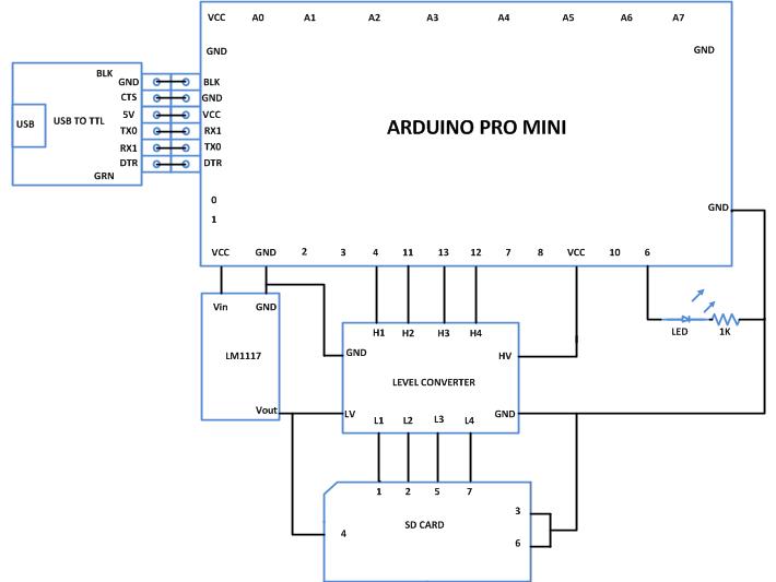
The SD memory card and the low voltage side of the Logic Level Converter should be provided with the 3.3V power supply and for that one can use any 3.3V regulator IC. A bi-color LED is suggested to connect across the 3.3V positive and MISO and MOSI lines of the SD card. The image of the memory card and the required circuitry that has been built for this particular project is shown in the following image. In the image one can see a potentiometer which is actually forms the circuit with an SMD variable regulator IC LM117 underneath it. It is recommended to use LM1117 which is a 3.3V regulator and which does not require other components to set the voltage as shown in the circuit diagram of this project.

Fig. 3: Interfacing SD Memory card using Level Contoller With Arduino
The Arduino pro-mini board has digital pins marked as 2, 3, 4 up to 13. Among the digital pins four pins namely 10, 11, 12 and 13 can be configured as SS, MOSI, MISO and SCK. The MISO of the memory card should be connected to the pin number 11, the MOSI should be connected to the pin number 12 and the SCK should be connected to the pin number 13 of the Arduino pro-min. The SS of the SD card should be connected to the pin which is defined as the SS pin of the Arduino in the code written. The image of the Arduino pro-mini board and the Arduino IDE version 1.0.3 for windows used in this project are shown in the following image;

Fig. 4: Typical Arduino Pro-Mini Board

Fig. 5: Arduino IDE Software Window
Since the arduino pro-mini board has no circuitary for interfacing it with the serial port or the USB port of the PC, an external USB to TTL converter board is required to connect it with the PC. This hardware helps in programming the arduino board and also helps in the serial communication with the PC through the USB port of the PC.

Fig. 6: External USB to TTL converter board for programming Arduino and serial communication
It is assumed that the reader has gone through the project how to get started with the arduino and done all the things discussed in it.
SD.begin()
The SD.begin() function used to initialize memory card so that it can be accessed through the SPI bus. The function has an optional parameter which is the number of the pin used as the Slave Select (SS) for the SD card. If the parameter is not provided during the function call the hardware SS pin will be used as default.
The function returns a value 1 on successful initialization of the SD card or otherwise it returns a value 0.
SD.open()
The function is used to open a file from the SD card. The file can be opened in either read mode or write mode. If a file is tried to open in write mode which does not exist, then a new file with the same name will be created and opened for reading. If a file which does not exist in the memory card and is tried to open for reading the function will return an error. If opening the file is successful then the function will return a variable of type ‘File’ which can then be used for reading, writing or closing the file.
The function has two parameters, the first one is the File _name and the second one is the Mode. The details of the two parameters are discussed below;
File_name
This is the first parameter of the function SD.open(), and it should be provided with the name of the file to be open. If the file is in a directory then the path of the file should be provided.
Mode
The second parameter of the function SD.open() represents either of the two modes in which the file can be opened. The parameter can be provided with the value FILE_READ or FILE_WRITE.
FILE_READ: If this value is provided to the second parameter of the function SD.open(), then the file will be opened in reading mode. If the file does not exist the function will return a value 0 otherwise 1 always.
FILE_WRITE: If this value is provided to the second parameter of the function SD.open(), then the file will be opened in writing mode. If the file does not exist in the SD card a new file with the same name will be created and opened for reading. If the file with the name provided in the parameter is opened successfully thebn the functiom will return 1 otherwise 0.
For example if a file with the name “test.txt” need to be opened in writing mode then the following statement can be used.
myFile = SD.open(“test.txt”, FILE_WRITE);
The above satatement will open the file “test.txt” and the file descriptor is returned to the variable ‘myFile’.
file.print()
The function print() is used to write a data to the file opened by the function SD.open. Suppose a file is opened by the SD.open () function using the following statement;
myFile = SD.open(“test.txt”, FILE_WRITE);
The file descriptor myFile can be passed as a parameter to the print() function so that it can write data into it. The following statement can be used to write a string “HELLO WORLD” in to a file named “test.txt” which has been opened for writing by the SD.open().
myFile.print(“HELLO WORLD”);
file.println()
The function println() writes a data each and every time to a new line in an opened file of the SD card.
file.read()
The function file.read() can be used to read a byte from the file which has already opened by the function SD.open() for reading. It simply returns the next byte from the SD card or a non-positive number if there is no data to be read.
For example to read a byte from the file which has been opened by using the following statement;
myFile = SD.open(“test.txt”, FILE_WRITE);
The read() function can be used as shown below;
var = myFile.read();
Where ‘var’ is a character variable into which the value of the byte returned by the function ‘read ()’ can be stored.
file.close()
This function is used to close a file which has been opened by the function SD.open(). Once the function is called the file descriptor no longer exists and hence can be used to access the same file again.
For example to close a file which has been opened with the help of the following statement
myFile = SD.open(“test.txt”, FILE_WRITE);
The function close() can be used to close the file as shown below;
myFile.close();
The data is transferred from a file created in the SD card and is monitored using the Serial monitor window with the help of the serial communicating functions written in the code. The functions used in this projects are namely Serial.begin(), Serial.println() and Serial.write(). The details of these functions and similar functions for the serial communication are already discussed in previous projects on how to do serial communication with the Arduino, how to send and receive serial data using arduino, how to do serial debugging with the Arduino.
When the coding is finished one can verify and upload the code to the Arduino board as explained in the project how to get started with the Arduino. The code will initialize the SD card, create a file “text.txt” in it and store a string inside that file which is again read back and displays on the Serial monitor. One can observe the data read from the file with the help of Serial monitor as explained in the project on how to do serial debugging with the Arduino.
The function delay() which has already been discussed in previous projects on how to start with Arduino and how to use digital input and output of Arduino is used here to generate a considerable delay between two consecutive reads.
Project Source Code
###


/*================================= EG LABS =======================================

The demonstration of simple read write using the Arduino on SD card


 The circuit:

 * SD card attached to SPI bus as follows:

 ** MOSI - pin 11

 ** MISO - pin 12

 ** CLK - pin 13

 ** CS - pin 4


 * LED attached from pin 6 to ground through a 1K resistor

================================== EG LABS =======================================*/


#include <SD.h>


File myFile;                                                                  // variable required to hold the file descriptor

const int chipSelect = 4;                                                     // the pin number which is needs to be used as a SS pin


void setup()

{

   Serial.begin(9600);                                                        // initialize the serial port at baud rate 9600

   Serial.print("Initializing SD card...");

   pinMode(10, OUTPUT);                                                       // It is a must to set the hardware SS pin as output eventhough it is not using


   while(!SD.begin(chipSelect));                                              // initialize the SD card

   Serial.println("card initialized.");


   while(!(myFile = SD.open("new.txt", FILE_WRITE)));                         // open a file for writing

   myFile.println("ENGINEERS GARAGE Inspiring creations");                    // write the string into the file

   myFile.close();                                                            // close the file


   while(!(myFile = SD.open("new.txt")));                                     // open the file for reading

   while (myFile.available())                                                 // read the file till the last byte

     Serial.write(myFile.read());

   myFile.close();                                                            // close the file


   pinMode(6, OUTPUT);                                                        // make the pin where the LED is connected as output

}


void loop()

{

  digitalWrite(6, HIGH);   // turn the LED on (HIGH is the voltage level)

  delay(1000);               // wait for a second

  digitalWrite(6, LOW);    // turn the LED off by making the voltage LOW

  delay(1000);

}

###
Circuit Diagrams
Project Components
Project Video
Filed Under: Arduino
Filed Under: Arduino

Questions related to this article?
👉Ask and discuss on EDAboard.com and Electro-Tech-Online.com forums.
Tell Us What You Think!!
You must be logged in to post a comment.