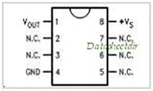
Fig. 1: Pin Diagram of LM35 Temperature Sensor IC
Fig 1: LM35 in IC form
The LM35 series are precision integrated-circuit temperature devices with an output voltage linearly-proportional to the Centigrade temperature. This device has an advantage over linear temperature sensors calibrated in Kelvin, as the user is not required to subtract a large constant voltage from the output to obtain convenient Centigrade scaling. The LM35 device does not require any external calibration or trimming to provide typical accuracies of ±¼°C at room temperature and ±¾°C over a full −55°C to 150°C temperature range. Lower cost is assured by trimming and calibration at the wafer level.
The famous LM35 linear temperature sensor is very useful to sense ambient/environment temperature. It is produced by National Semiconductor Corporation and offers a functional range from -40 degree Celsius to 150 degree Celsius. Sensitivity is 10mV per degree Celsius and the output voltage is proportional to the temperature. The output is linear to the temperature in degree Celsius and has high stability. The power supply required is 5V.
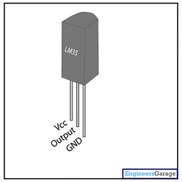
Fig. 2: Pin Diagram of LM35 Temeprature Sensor
Fig. 2 shows LM35 with three pins. When you bring heating element near this sensor, the output pin will show some voltage.
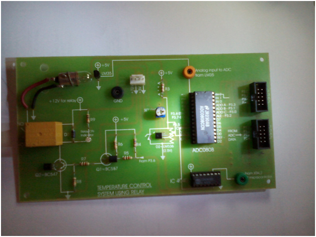
Fig. 3: Image showing 8051 Microcontroller based Temperature Control Module
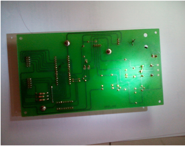
Fig. 4: Image showing soldering on 8051 Microcontroller based Temperature Control Module
Before proceeding with the coding part, let’s see some details of ADC0808 IC.
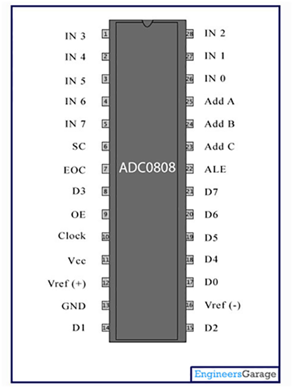
Fig. 5: Pin Diagram of ADC0808 Analog to Digital Converter IC
ADC0808 is an 8 bit analog to digital converter with eight input analog channels, i.e., it can take eight different analog inputs. The input which is to be converted to digital form can be selected by using three address lines. The voltage reference can be set using the Vref+ and Vref- pins. The step size is decided based on set reference value. Step size is the change in analog input to cause a unit change in the output of ADC. The default step size is 19.53mV corresponding to 5V reference voltage. ADC0808 needs an external clock to operate unlike ADC0804 which has an internal clock. It also needs some specific control signals for its operations like starting conversion and bringing data to output pins. When the conversion is complete, the EOC pin goes low to indicate the end of conversion and data is ready to be picked up.
P1=0xff; //P1 acts as an input port, reads the value of ADC
mybyte=mybyte-35;
Assembly language Programming
Assembly language Programming for Temperature controlling: We created this program under LIST file mechanism of Keil version 2.
; FUNCTION main (BEGIN)
; SOURCE LINE # 14
; SOURCE LINE # 15
; SOURCE LINE # 17
0000 7590FF MOV P1,#0FFH
; SOURCE LINE # 18
0003 D2B7 SETB EOC
; SOURCE LINE # 19
0005 C2B2 CLR ALE
; SOURCE LINE # 20
0007 C2B4 CLR START
; SOURCE LINE # 21
0009 C2B5 CLR OE
000B ?C0001:
; SOURCE LINE # 23
; SOURCE LINE # 24
; SOURCE LINE # 26
000B C2B0 CLR ADDR_C
; SOURCE LINE # 27
000D D2B1 SETB ADDR_B
; SOURCE LINE # 28
000F D2B3 SETB ADDR_A
; SOURCE LINE # 30
0011 120000 R LCALL delay
; SOURCE LINE # 31
0014 D2B2 SETB ALE
; SOURCE LINE # 32
0016 120000 R LCALL delay
; SOURCE LINE # 33
0019 D2B4 SETB START
; SOURCE LINE # 34
001B 120000 R LCALL delay
; SOURCE LINE # 35
001E C2B2 CLR ALE
; SOURCE LINE # 36
0020 C2B4 CLR START
0022 ?C0003:
; SOURCE LINE # 37
0022 20B7E6 JB EOC,?C0001
; SOURCE LINE # 38
; SOURCE LINE # 39
0025 D2B5 SETB OE
; SOURCE LINE # 40
;—- Variable ‘mybyte’ assigned to Register ‘R7’ —-
0027 AF90 MOV R7,P1
; SOURCE LINE # 41
0029 74DD MOV A,#0DDH
002B 2F ADD A,R7
; SOURCE LINE # 42
002C D3 SETB C
002D 9428 SUBB A,#028H
002F 400D JC ?C0005
; SOURCE LINE # 43
; SOURCE LINE # 44
0031 120000 R LCALL delay
; SOURCE LINE # 45
0034 D2B6 SETB RELAY
; SOURCE LINE # 46
0036 120000 R LCALL delay
0039 120000 R LCALL delay
; SOURCE LINE # 47
003C 80E4 SJMP ?C0003
003E ?C0005:
; SOURCE LINE # 49
; SOURCE LINE # 50
003E 120000 R LCALL delay
; SOURCE LINE # 51
0041 C2B6 CLR RELAY
; SOURCE LINE # 52
0043 120000 R LCALL delay
0046 120000 R LCALL delay
; SOURCE LINE # 53
; SOURCE LINE # 54
0049 80D7 SJMP ?C0003
; FUNCTION main (END)
; FUNCTION delay (BEGIN)
; SOURCE LINE # 61
; SOURCE LINE # 62
; SOURCE LINE # 64
;—- Variable ‘i’ assigned to Register ‘R6/R7’ —-
0000 E4 CLR A
0001 FF MOV R7,A
0002 FE MOV R6,A
0003 ?C0008:
0003 0F INC R7
0004 BF0001 CJNE R7,#00H,?C0012
0007 0E INC R6
0008 ?C0012:
0008 BE02F8 CJNE R6,#02H,?C0008
000B BF59F5 CJNE R7,#059H,?C0008
; SOURCE LINE # 65
000E ?C0011:
000E 22 RET
; FUNCTION delay (END)
List file of compiler always provide memory locations where mnemonics are residing. I do believe by modifying this code little bit, you can even display temperature value in LCD also. You can interface LCD to 8051 and use Port 2 and Port 0 for that interfacing.
Project Source Code
###
#include <reg51.h> //Header file for 8051 microcontrollervoid delay (void); //delay function prototype//Defining P3.0 bit as an ADDR_C of ADCsbit ADDR_C = P3^0; //Defining P3.1 bit as an EN which is Enable pin to//DC motorsbit ADDR_B = P3^1; //Defining P3.2 bit as an IN2 which is input2 pin to DC motorsbit ADDR_A = P3^3;sbit ALE = P3^2; //Defining P3.1 bit as an EN which is Enable pin to DC motorsbit OE = P3^5; //Defining P3.2 bit as an IN2 which is input2 pin to DC motorsbit START = P3^4;sbit EOC = P3^7;sbit RELAY = P3^6;void main (void){ //main function starts hereunsigned char mybyte;P1=0xff; //P1 acts as an input port, reads the value of ADCEOC=1;ALE=0;START=0;OE=0;while (1) //Do forever{ADDR_C=0;ADDR_B=1;ADDR_A=1;delay ();ALE=1;delay();START=1;delay();ALE=0;START=0;while (EOC !=1){OE=1;mybyte=P1;mybyte=mybyte-35;if (mybyte > 40){delay();RELAY=1;delay();delay();}else{delay();RELAY=0;delay();delay();}}}//while end} //End of main programvoid delay (void){ //delay function starts hereunsigned int i; //variable definedfor (i=0;i<=600;i++); //This for loop generates delay} //End of program###
Filed Under: Electronic Projects


Questions related to this article?
👉Ask and discuss on EDAboard.com and Electro-Tech-Online.com forums.
Tell Us What You Think!!
You must be logged in to post a comment.