To make Mobile charger we should know following things.
1) About Voltage divider.
2) Little knowledge about circuit. Like
· Resistor
· Diode
· Transformer
Let’s start the circuit making of Mobile/Battery charger.
Aim: To make a battery charger.
Material required: 220v-12v transformer, diode, resistor.
Procedure:
1) Connect 220v ac wire of transformer to ac socket with a fuse between them.

Fig. 1: Circuit Diagram showing Transformer Connected to AC Socket with Fuse
2) Connect the resistor as shown bellow.

Fig. 2: Circuit Diagram showing Connection of Resistor
3) This will give you 4.5 v in AC. To make it DC. You have to add H-Bridge.

Fig. 3: Circuit Diagram showing Connection of H-Bridge with Transformer
4) This is a very good charger for your battery to be charged. If you didn’t have any money to make a charger than you can make a variable voltage charger.
The circuit given above is the example of the variable voltage charger. This can be done by changing the value of the resistor. For getting the value of voltage as 6V. Put R1=R2. Let’s take R1 as 18ohm than R2 should be 18ohm. The relation between than is R1=R2.
Theory:
A voltage divider (also known as a potential divider). It is true example of potentiometer having two resistor in it. This is a device to make a reference voltage lesser than the input voltage. This make the science very big that any voltage can be derived by it by passing high voltage than the voltage we want. This is because output voltage which comes out is always lesser. A voltage divider referenced to ground is created by connecting two electrical resistors in series. The input voltage is applied across the series resistors R1 and R2 and the output is the voltage across only R2.

Proof:
Vin=I.(R1+R2)
Vout=I.R2

Proved that the ratio of Vout and Vin is equal to the ratio of R2 and sum of R1 and R2.
Calculation: Here we will calculate the that how I have made my charger.
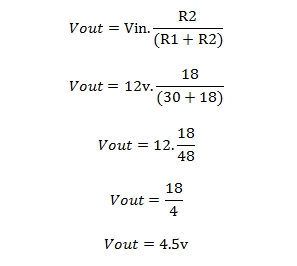
We have taken R1= 30 ohm
R2=18 ohm
Vin=12(converted 12V by transformer)

The outer voltage will be 4.5v which is required for our charger circuit.
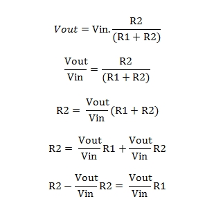
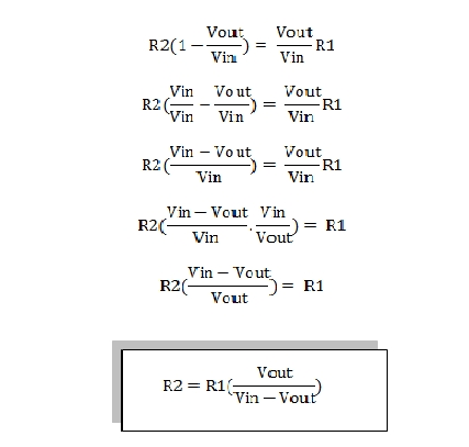
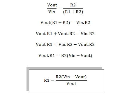
How to find R1 and R2?


From here you will get the value of R2.

Application:
Voltage dividers are used for adjusting the level of a signal, for bias of active devices in amplifiers and for measurement of voltages. A Wheatstone bridge and a multimeter both include voltage dividers. A potentiometer is used as a variable voltage divider in the volume control of a radio.
1. In finding temperature:
· Used as in sensor as the temperature changes resistance changes. As resistance of resistors changes voltage output changes. Due to the change in the voltage we get to know than we can find out the temperature very easily by calculating it. In this we have to only know the resistivity of the material we are using as the resistor.
2. As in battery charger:
· As you have seen in the above experiment the voltage divider is used in charger. By this way a huge amount of potential difference can be made very small. But in this there is a disappointing thing that it wastes lot of energy as useless. It can give heat or by any other reason it waste energy.
3. In Loudspeaker:
· In loudspeaker there is a potentiometer that is in voltage divider form. When we rotate its key the resistivity changes and then output voltage changes and then the volume of loudspeaker changes. if resistivity increases, the output voltage increases and then volume increases and if resistivity decreases, output voltage decreases and then volume decreases. It’s all because the potentiometer is a R2 resistor.
4. And much more are there.
Loading effect:
The voltage output of a voltage divider is not fixed but varies according to the load. To obtain a reasonably stable output voltage the output current should be a small fraction of the input current. The drawback of this is that most of the input current is wasted as heat in the divider.
Advantages of this battery charger:
1. It can change voltage from higher to lower in a very small ratio to very big ratio.
2. Only resistors are required to change the voltage. (diode are require to make AC into DC.
3. No heavy compounds are required. Like: Transistor, IC etc.
4. Very stable circuit.
5. Easily made by anyone and easily being calculated
6. Very small and easily fit in heavy circuit.
Disadvantages of this battery charger:
1. Most of the input current is wasted as heat in the divider.
2. The person having less knowledge about ohm law or circuit can result in the short circuit or blasting of resistors or something much higher can be happened.
3. If voltage divider input is connected to the battery then rate discharge of battery will be very high resulting in the damage of battery.
Filed Under: Tutorials


Questions related to this article?
👉Ask and discuss on EDAboard.com and Electro-Tech-Online.com forums.
Tell Us What You Think!!
You must be logged in to post a comment.