The AVR microcontroller boards which are provided with all the basic circuitry for the operation of the microcontroller which has been flashed with the Arduino boot-loader are called Arduino boards. The Arduino board has all the required circuitary to get the built-in AVR microcontroller running. When it comes to programming the Arduino board anyone who have basic knowledge of c programming can quickly get started with the Arduino IDE. Hence the Arduino forms an easy prototyping platform for both beginners and experts.
A microcontroller can communicate with the user by several means including LED display, sound generation, using the serial communication etc. The most commonly found output device in a microcontroller board is an LCD display module. The LCD module makes the system stand-alone since the systems don’t have to rely on an external PC where it can display the data send by using serial communication ports.
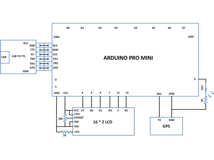
This particular project demonstrates how to make the Arduino as a stand-alone GPS receiver which can display the latitude and longitude of its position on a 16*2 LCD module. The GPS module is connected to the serial port of the Arduino and the data is continuously read from the GPS module, decoded and updated into readable format in a 16*2 LCD with a delay of one second.
The arduino board used in this project is the arduino pro-mini board and the IDE version of the arduino is 1.0.3 for windows. The image of the arduino pro-mini board and the arduino IDE are shown below;

Fig. 2: Typical Arduino Pro-Mini Board

Fig. 3: Arduino IDE Software Window
Since the arduino pro-mini board has no circuitary for interfacing it with the serial port or the USB port of the PC, an external USB to TTL converter board is required to connect it with the PC. This hardware helps in programming the arduino board and also helps in the serial communication with the USB port of the PC.

Fig. 4: External USB to TTL converter board for programming Arduino and serial communication
It is assumed that the reader has gone through the project how to get started with the arduino and tried out all the things discussed there. The commonly available 16*2 LCD module is used with this project and is interfaced with the Arduino board in 4 bit mode. The Arduino IDE provides so many functions to interface external devices like 16*2 LCD module in the form of standard Arduino library. One such library called <LiquidCrystal.h> which provides lot of functions to access the LCD module. The functions from the library used here are already discussed in the previous projects on how to interface an LCD, how to display sensor value on LCD, how to connect the LCD with the PC and how to make an LCD scrolling display.
The GPS module used in this project is SR-91 based GPS module which can communicate the data regarding the current location to a PC or microcontroller through the serial port. The image of the GPS module used for this project is shown below;

Fig. 5: SR-91 based GPS Module for serial communication
The GPS send the data in standard NMEA format which consist of the real time data regarding the current position. The format includes so many sentences and among them one particular sentence referred to as “Global Positioning System Fix Data” is extracted to read the North East coordinate using the Arduino.
The screenshot of the “Global Positioning System Fix Data” among the NMEA format data output from the GPS module is shown in the following image;

Each sentence has a sentence identifier, actual data separated by commas and a check sum which has to be extracted to make it in readable format. The details of the sentence “Global Positioning System Fix Data” is given in the following table;
| NAME |
EXAMPLE DATA |
DESCRIPTION |
|
Sentence Identifier |
$GPGGA |
Global Positioning System Fix Data |
|
Time |
170834 |
17:08:34 Z |
|
Latitude |
4124.8963, N |
41d 24.8963′ N or 41d 24′ 54″ N |
|
Longitude |
08151.6838, W |
81d 51.6838′ W or 81d 51′ 41″ W |
|
Fix Quality: |
1 |
Data is from a GPS fix |
|
Number of Satellites |
05 |
5 Satellites are in view |
|
Horizontal Dilution of Precision (HDOP) |
1.5 |
Relative accuracy of horizontal position |
|
Altitude |
280.2, M |
280.2 meters above mean sea level |
|
Height of geoid above WGS84 ellipsoid |
-34.0, M |
-34.0 meters |
|
Time since last DGPS update |
blank |
No last update |
|
DGPS reference station id |
blank |
No station id |
|
Checksum |
*75 |
Used by program to check for transmission errors |
Fig. 6: Pin Out Of Xbee Module
The code written for this project on Arduino reads the serial data from the GPS module using the serial communication functions provided by the Arduino library. The functions like Serial.begin() which helps to initialize the serial port with a given baud rate, Serial.write() to send a data to the serial port, Serial.available() and Serial.read() functions to read data from the serial port are used in this project and they are already discussed in previous projects on how to do serial communication with the Arduino, how to send and receive serial data using arduino and how to do serial debugging with the Arduino. As the code reads the data from the GPS module it looks for a particular sentence which consists of the latitude and longitude details and displays the latitude and longitude in a readable format in the 16*2 LCD. The method of getting the required latitude and longitude data from the NMEA format output from the GPS is explained in the previous project on how to interface the Arduino with 16*2 LCD.
When the coding is finished one can verify and upload the code to the Arduino board as explained in the project how to get started with the Arduino and the geographical coordinate can be read from the 16*2 LCD. The Tx pin of the GPS module should be connected to the RX1 pin of the Arduino pro-mini board and the ground of both the GPS module and the Arduino board should be shorted together. When testing, make sure that the GPS antenna is placed outside the building through a window or door in such a way that it is having a clear view of the horizon.
Project Source Code
###


/*============================ EG LABS ===================================//


 Demonstration on how to use PS2 MOUSE with an arduino board

 The circuit:

 LCD:

 * LCD RS pin to digital pin 12

 * LCD Enable pin to digital pin 11

 * LCD D4 pin to digital pin 7

 * LCD D5 pin to digital pin 6

 * LCD D6 pin to digital pin 5

 * LCD D7 pin to digital pin 4

 * LCD R/W pin to ground

 * 10K resistor:

 * ends to +5V and ground

 * wiper to LCD pin 3

 * LED anode attached to digital output 9

 * LED cathode attached to ground through a 1K resistor


 GPS:

 TX PIN OF GPS TO RX1 PIN OF ARDUINO

 SHORT THE GROUND PINS OF ARDUINO AND GPS


============================== EG LABS ===================================*/


#include <LiquidCrystal.h>


// initialize the library with the numbers of the interface pins

LiquidCrystal lcd(12, 11, 7, 6, 5, 4);


// give the pin a name:

int led = 9;

// incoming serial byte

int inByte = 0;


void setup()

{

   // set up the lcd's number of columns and rows:

  lcd.begin(16, 2);

  lcd.print("ENGINEERS GARAGE");

  lcd.setCursor(0, 1);

  lcd.print(" GPS  INTERFACE ");


  // initialize the led pin as an output.

  pinMode ( led, OUTPUT );


  // start serial port at 9600 bps

  // wait for a while till the serial port is ready

  delay ( 3000 );

  Serial.begin(4800);

  digitalWrite( led, HIGH );

}


void loop ()

{

//==================== searching for "GG" ===================//

    do

    {

        do

        {

            while ( !Serial.available() );

        } while ( 'G' != Serial.read() );                    // reading a character from the GPS


        while(!Serial.available());

    } while ( 'G' != Serial.read() );

//==================== searching for "GG" ===================//


//============== seeking for north cordinate ==============//

    do

    {

        while ( !Serial.available() );

    } while ( ',' != Serial.read() );                        // reading a character from the GPS


    do

    {

        while ( !Serial.available() );

    } while ( ',' != Serial.read() );

//============== seeking for north cordinate ==============//


//============== printing the north cordinate ===============//

    lcd.clear();

    lcd.print(" N: ");

    do

    {

        while ( !Serial.available() );

        inByte = Serial.read();                              // reading a character from the GPS

        lcd.write ( inByte );                                // printing the Latitude

    } while ( ',' != inByte );

//============== printing the north cordinate ===============//


//============== seeking for east cordinate ==============//

    do

    {

        while ( !Serial.available() );

    } while ( ',' != Serial.read() );                       // reading a character from the GPS

//============== seeking for east cordinate ==============//


//============== printing the east cordinate ===============//

    lcd.setCursor(0, 1);

    lcd.print(" E: ");

    do

    {

        while ( !Serial.available() );

        inByte = Serial.read();                            // reading a character from the GPS

        lcd.write ( inByte );                              // printing the Longitude

    } while ( ',' != inByte );

//============== printing the east cordinate ===============//


    delay ( 1000 );

}

###
Circuit Diagrams
Project Components
Project Video
Filed Under: Arduino
Filed Under: Arduino

Questions related to this article?
👉Ask and discuss on EDAboard.com and Electro-Tech-Online.com forums.
Tell Us What You Think!!
You must be logged in to post a comment.