Engineers Garage

  • Electronic Projects & Tutorials
    • Electronic Projects
      • Arduino Projects
      • AVR
      • Raspberry pi
      • ESP8266
      • BeagleBone
      • 8051 Microcontroller
      • ARM
      • PIC Microcontroller
      • STM32
    • Tutorials
      • Audio Electronics
      • Battery Management
      • Brainwave
      • Electric Vehicles
      • EMI/EMC/RFI
      • Hardware Filters
      • IoT tutorials
      • Power Tutorials
      • Python
      • Sensors
      • USB
      • VHDL
    • Circuit Design
    • Project Videos
    • Components
  • Articles
    • Tech Articles
    • Insight
    • Invention Stories
    • How to
    • What Is
  • News
    • Electronic Product News
    • Business News
    • Company/Start-up News
    • DIY Reviews
    • Guest Post
  • Forums
    • EDABoard.com
    • Electro-Tech-Online
    • EG Forum Archive
  • DigiKey Store
    • Cables, Wires
    • Connectors, Interconnect
    • Discrete
    • Electromechanical
    • Embedded Computers
    • Enclosures, Hardware, Office
    • Integrated Circuits (ICs)
    • Isolators
    • LED/Optoelectronics
    • Passive
    • Power, Circuit Protection
    • Programmers
    • RF, Wireless
    • Semiconductors
    • Sensors, Transducers
    • Test Products
    • Tools
  • Learn
    • eBooks/Tech Tips
    • Design Guides
    • Learning Center
    • Tech Toolboxes
    • Webinars & Digital Events
  • Resources
    • Digital Issues
    • EE Training Days
    • LEAP Awards
    • Podcasts
    • Webinars / Digital Events
    • White Papers
    • Engineering Diversity & Inclusion
    • DesignFast
  • Guest Post Guidelines
  • Advertise
  • Subscribe

How To Make Dynamic Sensor Display On LCD Using Arduino- (Part 15/49)

By Ajish Alfred July 4, 2013

Microcontroller based devices are widely used in different kind of sensing applications. Even though the microcontrollers are purely digital devices which work on logic0 and logic1 voltages they can read analog voltages as well. Most of the microcontrollers have built-in Analog to Digital Converter (ADC) modules which helps them in reading analog voltage inputs.The microcontroller based devices have several means by which it can communicate the sensed value with the user. It can use LED arrays, it can vary the intensity of a sound, and it can even communicate with a PC using serial communication protocol. But the most effective and commonly used method is to use dynamic display on an LCD connected with in the system.

The LCD module is the most common output unit in a microcontroller board. It is very effective since it can display messages, values, clock etc. Special kinds of LCD drivers are used to drive the LCD. The LCD modules can display not only ASCII characters but custom characters also. The user can store the pixel array corresponding to the custom character in an LCD module. The stored custom character can be made to display by sending the corresponding value to the LCD module. The custom characters are used for the dynamic display in an LCD board.The Arduino is an easy-prototyping platform where the hardware is very simple and the coding and IDE is very easy to start with. Since the basic Arduino board does not have a built –in LCD module to display data one should connect it externally to display data like strings, sensor values etc. The libraries in the Arduino IDE help in accessing the LCD module very easily. This project demonstrates how to use a 16x2 LCD with the Arduino board for the dynamic display of a sensor value. The code has been written using the library functions and the sensor used here is a simple potentiometer which can vary its voltage in its variable pin.


This project makes use of the custom characters that can be generated in an LCD module. The LCD module has two or more controllers which helps in displaying the characters corresponding to the ASCII value which is send by the microcontroller. The ASCII character patterns are stored in the internal CGROM of the LCD controllers. The LCD modules also provide a CGRAM where the user can store the custom characters and display them. The method of generating custom characters is well explained in a previous project on how to create custom characters in an LCD.

In this project the Arduino pro-mini board is used which is then programmed with the help of Arduino IDE version 1.0.3 on windows operating system. The image of the Arduino pro-mini board and the Arduino IDE is shown in the following;

Typical Arduino Pro-Mini Board

Fig. 2: Typical Arduino Pro-Mini Board


Arduino IDE Software Window

Fig. 3: Arduino IDE Software Window

Another hardware which can perform the USB to TTL conversion is used to upload the program into the arduino board. One has to work out the character of the custom character that needs to be displayed in the LCD screen as explained in the project on how to create custom characters in an LCD. The custom characters which are displayed in this project are shown in the following image.

Custom Created Characters On LCD Using Arduino Circuit On Breadboard

Fig. 4: Custom Created Characters On LCD Using Arduino Circuit On Breadboard


External USB To TTL Converter Board For Programming Arduino And Serial Communication

Fig. 5: External USB to TTL converter board for programming Arduino and serial communication

It is assumed that the reader has gone through the project how to get started with the arduino and done all the things discussed in it. The arduino pro-mini board can have a maximum of eight analog pins which can be configured as analog input pins. The pins are marked in the board as A0, A1, and A2 up to A7. They are actually the input channels to the built-in ADC which can read the analog value and convert them to the digital equivalent. Some pro-mini boards have lesser number of analog pins.

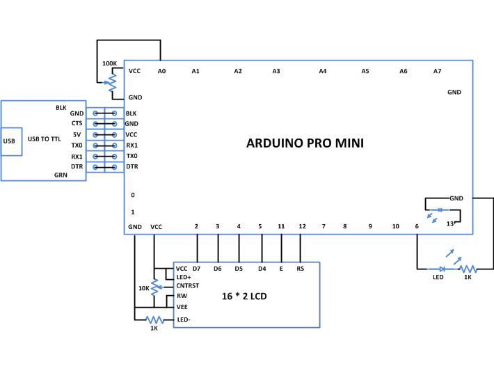
In this particular project the variable pin of a potentiometer is connected to the analog pin;in this project the pin A0. The other two pins of the potentiometer is connected to the VCC and GND so that as the variable moves it can divide the entire supply voltage and provide it as the analog input voltage for the arduino board. An LED is connected to the analog output pin through a current limiting resistor; in this project it is connected to the pin 6. The code continuously reads the value from the potentiometer and writes the corresponding value to change the brightness of the LED connected to the pin 6.The built-in function in the arduino IDE analogRead() helps in reading the analog value from an analog input pin and another function called andanalogWrite() helps in writing an analog value to the analog output pin. The details of the functions and the method of analog read and write are already discussed in a previous project on how to use the analog input and output of the arduino.

The Arduino IDE has a library called <LiquidCrystal.h> which provides lot of functions to access the LCD module. Few of those functions which are very useful is small applications are already discussed in the previous project on how to interface an LCD, how to display sensor value on LCD, how to connect the LCD with the PC  and how to make an LCD scrolling display.

The code written for this project has a function lcd.createChar() which helps to create the custom characters in an LCD screen. The details of the lcd.createChar() function are discussed in the following section.

lcd.createChar()

The function lcd.createChar() can be used to write a custom character to the required location in the CGRAM. The function has two parameters in which the first parameter is the location in the CGRAM memory where the character array corresponding to the custom character need to be stored and the second parameter is the character array itself. For example if there is a custom character array called ‘cc’ and it need to be stored in the 5th location of CGRAM one can use the following statement;

lcd.createChar(5, cc);

The above statement writes the character array to the 5th location of the CGRAM of the LCD controller from where it can be displayed by calling the lcd.write() function discussed in the projects on how to connect the LCD with the PC and how to make an LCD scrolling display.

lcd.write(5);

The code reads the analog calculate the analog voltage from it and then displays that much custom characters in the LCD screen. The code also glows an LED with the brightness which is equivalent to the value read from the analog input pin as discusses in a previous project on how to use analog input and output of the Arduino. Once done with the coding one can verify and upload the code to the Arduino board as explained in the project how to get started with the Arduino and the brightness of the LED can be observed to vary as the variable of the potentiometer moves. The voltage read from the analog input pin will be indicated using the dynamic display in the LCD module.

Project Source Code

###


/*================================= EG LABS =======================================

 Dynamic display of sensor value in an LCD

 The circuit:

 * LED attached from pin 5 to ground through a 1K resistor 
     LCD:

 * LCD RS pin to digital pin 12

 * LCD Enable pin to digital pin 11

 * LCD D4 pin to digital pin 5

 * LCD D5 pin to digital pin 4

 * LCD D6 pin to digital pin 3

 * LCD D7 pin to digital pin 2

 * LCD R/W pin to ground

 * 10K resistor:

 * ends to +5V and ground

 * wiper to LCD pin 3

 * LED anode attached to digital output 6

 * LED cathode attached to ground through a 1K resistor

//================================= EG LABS =======================================*/

// include the library code:

#include <LiquidCrystal.h>

// initialize the library with the numbers of the interface pins

LiquidCrystal lcd(12, 11, 5, 4, 3, 2);

//----------------- store the custom characters in arrays ---------------------//

byte cc1[8] = 

              {

                0b00000,

                0b00000,

                0b00000,

                0b00000,

                0b00000,

                0b00000,

                0b00000,

                0b11111

              };

byte cc2[8] = 

              {

                0b00000,

                0b00000,

                0b00000,

                0b00000,

                0b00000,

                0b00000,

                0b11111,

                0b11111

              };

byte cc3[8] = 

              {

                0b00000,

                0b00000,

                0b00000,

                0b00000,

                0b00000,

                0b11111,

                0b11111,

                0b11111

              };

byte cc4[8] = 

              {

                0b00000,

                0b00000,

                0b00000,

                0b00000,

                0b11111,

                0b11111,

                0b11111,

                0b11111

              };

byte cc5[8] = 

              {

                0b00000,

                0b00000,

                0b00000,

                0b11111,

                0b11111,

                0b11111,

                0b11111,

                0b11111

              };

//----------------- store the custom characters in arrays ---------------------//

const int analogInPin = A0;  // Analog input pin that the potentiometer is attached to

const int analogOutPin = 6;  // Analog output pin that the LED is attached to

int potvalue = 0;

int outputvalue=0;

int no_bars = 0;

int bar_height = 0;

void setup()

{

  //---- create custom characters ----//

  lcd.createChar(1, cc1);

  lcd.createChar(2, cc2);

  lcd.createChar(3, cc3);

  lcd.createChar(4, cc4);

  lcd.createChar(5, cc5);

  //---- create custom characters ----//

  // set up the lcd's number of columns and rows: 

  lcd.begin(16, 2);

}

void loop()

{

  lcd.print("EG LABS ");  

  // read the analog in value:

  potvalue = analogRead(analogInPin);        

  // map it to the range of the analog out:

  outputvalue = map(potvalue, 0, 1023, 0, 255); 

  // change the analog out value:

  analogWrite(analogOutPin, outputvalue);      

  // calculate the input voltage

  no_bars = (outputvalue * 5) / 255;

  // display custom bars according to the input voltage

  for(bar_height = 1; bar_height <= no_bars; bar_height ++)

      lcd.write(bar_height);                    // dispaly custom character

  // keep the same display for a while and then clear

  delay(200);

  lcd.clear();

}

###


Circuit Diagrams

Circuit-Diagram-Making-Dynamic-Sensor-Display-LCD-Using-Arduino

Project Components

  • Arduino Pro Mini
  • LCD
  • LED
  • Resistor

Project Video


Filed Under: Arduino Projects
Tagged With: Arduino, lcd, sensor display
 

Next Article

← Previous Article
Next Article →

Questions related to this article?
👉Ask and discuss on Electro-Tech-Online.com and EDAboard.com forums.


Tell Us What You Think!! Cancel reply

You must be logged in to post a comment.

EE TECH TOOLBOX

“ee
Tech Toolbox: Internet of Things
Explore practical strategies for minimizing attack surfaces, managing memory efficiently, and securing firmware. Download now to ensure your IoT implementations remain secure, efficient, and future-ready.

EE Learning Center

EE Learning Center
“engineers
EXPAND YOUR KNOWLEDGE AND STAY CONNECTED
Get the latest info on technologies, tools and strategies for EE professionals.

HAVE A QUESTION?

Have a technical question about an article or other engineering questions? Check out our engineering forums EDABoard.com and Electro-Tech-Online.com where you can get those questions asked and answered by your peers!


RSS EDABOARD.com Discussions

  • How to preserve hierarchical instance names like \adder_1/U1 in flattened gate-level netlist in Design Compiler?
  • Can anyone provide a guide or tutorial for Candece simulation?
  • Voltage mode pushpull is a nonsense SMPS?
  • High Side current sensing
  • MOSFET thermal noise in Weak vs Strong inversion

RSS Electro-Tech-Online.com Discussions

  • Is AI making embedded software developers more productive?
  • Can I make two inputs from one??
  • Why can't I breadboard this oscillator?
  • Cataract Lens Options?
  • Back to the old BASIC days

Featured – RPi Python Programming (27 Part)

  • RPi Python Programming 21: The SIM900A AT commands
  • RPi Python Programming 22: Calls & SMS using a SIM900A GSM-GPRS modem
  • RPi Python Programming 23: Interfacing a NEO-6MV2 GPS module with Raspberry Pi
  • RPi Python Programming 24: I2C explained
  • RPi Python Programming 25 – Synchronous serial communication in Raspberry Pi using I2C protocol
  • RPi Python Programming 26 – Interfacing ADXL345 accelerometer sensor with Raspberry Pi

Recent Articles

  • GigaDevice launches GD32C231 MCU series with 48MHz Cortex-M23 core and 64KB Flash
  • Advanced Energy releases 425 W CF-rated medical power supply in 3.5 x 6 x 1.5-inch format”
  • LEM combines shunt and Hall effect sensing in 2000 A current measurement unit
  • What is AWS IoT Core and when should you use it?
  • AC-DC power supply extends voltage range to 800 V DC

EE ENGINEERING TRAINING DAYS

engineering

Submit a Guest Post

submit a guest post
Engineers Garage
  • Analog IC TIps
  • Connector Tips
  • Battery Power Tips
  • DesignFast
  • EDABoard Forums
  • EE World Online
  • Electro-Tech-Online Forums
  • EV Engineering
  • Microcontroller Tips
  • Power Electronic Tips
  • Sensor Tips
  • Test and Measurement Tips
  • 5G Technology World
  • Subscribe to our newsletter
  • About Us
  • Contact Us
  • Advertise

Copyright © 2025 WTWH Media LLC. All Rights Reserved. The material on this site may not be reproduced, distributed, transmitted, cached or otherwise used, except with the prior written permission of WTWH Media
Privacy Policy

Search Engineers Garage

  • Electronic Projects & Tutorials
    • Electronic Projects
      • Arduino Projects
      • AVR
      • Raspberry pi
      • ESP8266
      • BeagleBone
      • 8051 Microcontroller
      • ARM
      • PIC Microcontroller
      • STM32
    • Tutorials
      • Audio Electronics
      • Battery Management
      • Brainwave
      • Electric Vehicles
      • EMI/EMC/RFI
      • Hardware Filters
      • IoT tutorials
      • Power Tutorials
      • Python
      • Sensors
      • USB
      • VHDL
    • Circuit Design
    • Project Videos
    • Components
  • Articles
    • Tech Articles
    • Insight
    • Invention Stories
    • How to
    • What Is
  • News
    • Electronic Product News
    • Business News
    • Company/Start-up News
    • DIY Reviews
    • Guest Post
  • Forums
    • EDABoard.com
    • Electro-Tech-Online
    • EG Forum Archive
  • DigiKey Store
    • Cables, Wires
    • Connectors, Interconnect
    • Discrete
    • Electromechanical
    • Embedded Computers
    • Enclosures, Hardware, Office
    • Integrated Circuits (ICs)
    • Isolators
    • LED/Optoelectronics
    • Passive
    • Power, Circuit Protection
    • Programmers
    • RF, Wireless
    • Semiconductors
    • Sensors, Transducers
    • Test Products
    • Tools
  • Learn
    • eBooks/Tech Tips
    • Design Guides
    • Learning Center
    • Tech Toolboxes
    • Webinars & Digital Events
  • Resources
    • Digital Issues
    • EE Training Days
    • LEAP Awards
    • Podcasts
    • Webinars / Digital Events
    • White Papers
    • Engineering Diversity & Inclusion
    • DesignFast
  • Guest Post Guidelines
  • Advertise
  • Subscribe