The SD memory card comes in large storage capacities from 1 GB up to 32 GB are available. They are used mostly in costly devices like digital camera, media players etc. They are also found in low cost and simple micro-controller based systems. The SD memory cards are interfaced in high end devices using SD bus which provides very high speed data transfer between the device and the memory card. They also can be interfaced with a device using the low speed and comparatively simple SPI bus and that is the reason why the micro-controller system developers are interested in it.
This project demonstrate how to store the data continuously from an analog sensor into a memory card for predefined period of time and display the same data in a Serial monitoring software. In this particular project the variable pin of a potentiometer is connected to provide analog voltage for the Arduino board to read and store in the SD card which can be easily replaced with a real sensor in future projects.
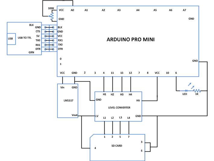
This particular project uses the Arduino pro-mini board which has a very small size and can be connected with bread board compatible connectors. The Arduino pro-mini board has digital pins marked as 2, 3, 4 up to 13. Among the digital pins four pins namely 10, 11, 12 and 13 can be configured as SS, MOSI, MISO and SCK. The MISO of the memory card should be connected to the pin number 11, the MOSI should be connected to the pin number 12 and the SCK should be connected to the pin number 13 of the Arduino pro-min. The SS of the SD card should be connected to the pin which is defined as the SS pin of the Arduino in the code written. The image of the Arduino pro-mini board and the Arduino IDE version 1.0.3 for windows used in this project are shown in the following image;

Fig. 2: Typical Arduino Pro-Mini Board

Fig. 3: Arduino IDE Software Window
Since the arduino pro-mini board has no circuitary for interfacing it with the serial port or the USB port of the PC, an external USB to TTL converter board is required to connect it with the PC. This hardware helps in programming the arduino board and also helps in the serial communication with the PC through the USB port of the PC.

Fig. 4: External USB to TTL converter board for programming Arduino and serial communication
It is assumed that the reader has gone through the project how to get started with the arduino and done all the things discussed in it.

Fig. 5: Logic Level Converter Module Circuit
The SD memory card and the low voltage side of the Logic Level Converter should be provided with the 3.3V power supply and for that one can use any 3.3V regulator IC. A bi-color LED is suggested to connect across the 3.3V positive and MISO and MOSI lines of the SD card. The image of the memory card and the required circuitry that has been built for this particular project is shown in the following image. In the image one can see a potentiometer which is actually forms the circuit with an SMD variable regulator IC LM117 underneath it. It is recommended to use LM1117 which is a 3.3V regulator and which does not require other components to set the voltage as shown in the circuit diagram of this project.

Fig. 6: SD memory card connected to Logic Level Converter with 3.3V regulator IC Circuit Set up
The Arduino IDE provides a library called <SD.h> which has lot of functions to access the SD memory card. The library is able to access the FAT16 or FAT32 filesystem of the SD card using the AVR microcontroller of the Arduino board so that the files can be read, modify or write. The functions used in this particular project are SD.begin(), SD.open(), file. println(), file.read(), and file.close() from the library <SD.h> and the details regarding them are explained in a previous project on how to interface SD card with Arduino.
The Arduino board has several digital pins which can be configured as digital I/O pins and among them some can also be used as analog output pins. There are dedicated analog input pins also in most of the Arduino boards. The Arduino pro-mini board has 8 analog input pins marked as A0, A1 up to A7. In this particular project the variable pin of a potentiometer is connected at the analog input pin A0.
The Arduino IDE provides functions to access analog input and analog output of the board. The code written for this project uses the built-in function provided by the Arduino IDE namely analogRead() and analogWrite(). The functions are already used in the previous projects on how to use analog input and analog output of Arduino board, how to use Arduino to display sensor values, how to make dynamic sensor display using Arduino, how to save sensor values in the EEPROM of the Arduino.
The code create or open a file “sensor.txt” and store 50 sensor values which has been read with a delay of half a second between them. Once the 50 values are read the code reads the entire file and displays it in the Serial monitor. The data is transferred from a file from the SD card and is monitored using the Serial monitor window with the help of the serial communicating functions written in the code. The functions used in this projects are namely Serial.begin(), Serial.println() and Serial.write(). The details of these functions and similar functions for the serial communication are already discussed in previous projects on how to do serial communication with the Arduino, how to send and receive serial data using arduino, how to do serial debugging with the Arduino.
When the coding is finished one can verify and upload the code to the Arduino board as explained in the project how to get started with the Arduino. The code will initialize the SD card, create a file “sensor.txt” and store 50 sensor values in it and read back the entire file. One can observe the data read from the file with the help of Serial monitor as explained in the project on how to do serial debugging with the Arduino.
Project Source Code
###


/*================================= EG LABS =======================================

The demonstration of storing and reading back sensor data with an SD card

 The circuit:

 * SD card attached to SPI bus as follows:

 ** MOSI - pin 11

 ** MISO - pin 12

 ** CLK - pin 13

 ** CS - pin 4

 * LED attached from pin 6 to ground through a 1K resistor

================================== EG LABS =======================================*/

#include <SD.h>

File myFile;

const int chipSelect = 4;                                                 // define the chip select pin number

const int analogInPin = A0;                                       // define the analog input pin number where the potentiometer is attached to

const int analogOutPin = 6;                                        // define the analog output pin where the LED is attached to

int potvalue = 0;                                                     // define a variable to store the analog value read from the potentiometer

int outputvalue=0;                                                 // define a variable to store the analog output value that need to be written into the LED

int i = 0;                                                                  // define a variable to use in loops

void setup()

{

   Serial.begin(9600);                                                           // initialize the serial port

   Serial.print("Initializing SD card...");

   pinMode(10, OUTPUT);                                            // must initialize the hardware SS pin as output eventhough it is not using.

   while(!SD.begin(chipSelect));                                        // initialize the SD card

   Serial.println("card initialized.");

   for(i = 0; i < 50; i ++)                                                      // loop for storing 50 sensor values

   {

     potvalue = analogRead(analogInPin);                                         // read the pot value

     while(!(myFile = SD.open("sensor.txt", FILE_WRITE)));                       // open/create a file sensor.txt

     // write the data into the file //

     myFile.print(i);

     myFile.print("     ");

     myFile.println(potvalue);

     myFile.close();

    // write the data into the file //

     outputvalue = map(potvalue, 0, 1023, 0, 255);          // map the value into tha range of 0 to 255 so that it can be written to analog output

     analogWrite(analogOutPin, outputvalue);                  // write the value to generate equivalent analog output

     delay(500);                                                                 // wait for a while before reading the next analog value

   }

   // open the file and read the data //

###
Circuit Diagrams
Project Components
Project Video
Filed Under: Arduino
Filed Under: Arduino

Questions related to this article?
👉Ask and discuss on Electro-Tech-Online.com and EDAboard.com forums.
Tell Us What You Think!!
You must be logged in to post a comment.